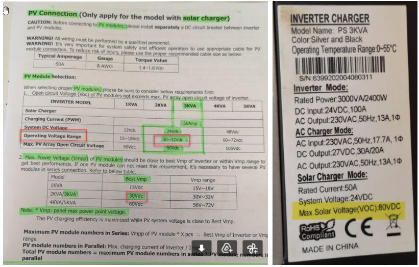
I have an Axpert 3KVA Inverter with PWM charge controller.
It has a Solar Charge Mode rated current of 50A and PV Array input Operating Voltage Range of 30~32Vdc and a Max. PV Array Open Circuit Voltage (Voc) of 80Vdc.
Question:
So the ideal PV [Solar Panel(s)] for the Inverter would have to be quite small (probably 200Watt or smaller PV) to achieve the “ideal” 30~32Vdc input to the Inverter.
If I look at higher wattage PVs like Jinko, JA Solar or Canadian Solar with between 360 Watt and 450 Watt (STC) then they have an average Voc of about 42Vdc (and +/- 11Amp per PV).
Question: Can I use these higher wattage PVs with my Axpert Inverter as long as the PV’s Voc is below 80Vdc and the Amps is below 50 Amp?
Example: If I get 1 x 475 Watt PV it will have a Voc of 42Vdc and max input current of 11.2 Amps, would the Inverter be “OK” with this input and just clip the voltage down to 32Vdc so effectively one just gets a lower Wattage from each PC (Panel is 42Vdc but Inverter only uses max 32Vdc (and “clips” the rest), so Panel will only give 32Vdc x 11.2 Amp (358 Watt) to the Inverter although it is capable of delivering [42V x 11.2A = 470 Watt under STC], so one only loses efficiency (not getting max Wattage out of each PV) but it won’t damage the Axpert Inverter if within the “Voc” and Max Amps limits of the inverter?
The Reason I want to rather buy higher Wattage PVs is that they cost less per KW, uses less footprint space and can also be used with other larger and newer Inverters so one can re-apply those higher wattage PVs later if the Axpert stops working in future (no sense in buying < 200W Panels now and cannot use them on any new Inverters in future).
Yup. So if you have a 360W module, making 11A at 42V, then the PWM is going to pull it down to 25V (ish, whatever battery voltage is), and you’re going to get max 275W (25V times 11A) out of the module.
If you can find a 60-cell 275W module you will do better. I see some on GeeWiz’s site.
It is theoretically just above the max Voltage. As soon as there’s a load on the panels the voltage drops. And it is rare that there is never a load…
The advantage of using higher voltages is that the current is low. So you don’t need fat PV panel cables.
Hmmm, MOSFETs don’t have a lot of mercy when it comes to voltage. There is also no storage or conversion in a PWM controller. Essentially just a MOSFET that connects the panel to the battery when the battery voltage is below a set value and disconnects when above (with some hysteresis). So increasing the voltage does not increase the power transferred. And in the cycle when the the MOSFET is open you have Voc over it(technically probably Voc-Vbat).
I disagree. A PWM controller chops the DC with a variable mark-to-space ratio. This then is smoothed and effectively the voltage is reduced (for a specific load).
They are efficient since there is little time spent between the on & off voltages where the power losses are greatest.
My point about using as many PV panels in series is to avoid high currents in the PV cables, not theoretically because it’s more efficient.
I have 4 x 350W panels that are connected with 2 in series. The power delivered by these on a sunny day is 1.1 kW. (i.e. 75V @ 15A)
If I were to connect all panels in parallel the current would be 30A. That’s a fair amount of current for a 4mm² cable.
The maximum current for this cable is 36A (Rating based on two touching cables, installed in a duct.- Assumed ambient air temperature is 30°C and maximum conductor temperature is 70°C.0
I don’t think the mark/space thing matters. The point is that the max amps you will get is whatever the panel makes. There is no swapping volts for amps (like with an MPPT), which means any voltage higher than about Vbat+5 is basically a waste. It would be much better to place panels in parallel to increase the amperage.
With a PWM controller you won’t be running at 75V. In the current discussion, the battery is 24V.
But a PWM controller is not a DC/DC converter. In other words, it’s the kind of setup you have prior to 1:12 in that video. There is no inductor in there.
Once you add the diode at 2:25 you have a full (asynchronous) buck converter.
I do apologise if I missed something in this conversation, but as far as I know the PWM-type in the Axpert has no inductor.
I have seen some clever use of PWM on small DC borehole pumps. The windings of the DC motor is used as the inductor, so that the solar controller needs only a simply PWM-type tracker. But that’s an aside not really relevant here.
Edit: To be specific, a PWM controller is not much different to those old on/off types we used 30 years ago. Those old types would switch off when the voltage reached a specific point, and on again when it dropped below a certain point. The PWM does essentially the same, except that it modules a PWM signal according to how close the voltage is to the target. The switching is now somewhere above 22khz (to avoid hearing the thing), but the principle is the same.
But I guess you want to know if you can use a 72-cell 360W module? Sure… why not. It’s within the specs. And it probably costs about the same as the older 60-cell too.
Just to summarize the original question: (From a technical and electrical perspective only - not from a cost saving or practicality perspective): Will an input Voltage of higher than 32 Vdc (but lower than 80 Vdc) from a single PV Panel damage my Axpert Inverter or not?
The Expert Inverter has a Solar Charge Mode rated current of 50A and “ideal” PV Array input Operating Voltage Range of 30~32 Vdc BUT a Maximum PV Array Open Circuit Voltage (Voc) is listed as 80 Vdc (i.e.: higher than 32V dc), so even though this is not the most efficient input Voltage (I accept that) it CAN still safely function with a higher input Voltage from the PV without being damaged?
If my assumption is correct, assuming that I will just use one PV as a start then I should be able to use a higher wattage PV (higher than the “ideal” 250 Watt PV for this Inverter, say a 450 Watt PV) as long as the PV’s Voc is below the maximum 80Vdc (and of course the total output Amps of the PV is below 50 Amps) without it damaging the Inverter and its PWM Charge Controller. So “excessive” input Voltage (above 32Vdc) would just be discarded (or clipped or whatever the right term is) and the PWM Charge Controller will charge the 24Vdc Battery Bank without issues or damage to the Inverter.
@Richard_Mackay Not legacy on this inverter! “Maximum PV Array Open Circuit Voltage (Voc) is listed as 80 Vdc” it is maximum recommended by the manufacturer! See below!