Lithium cells bulging - what are the opinions?

Interesting.
@Louisvdw indicated that charging with a sub-1A was not really an option as about 1A was about as low as can be practically achieved.
@plonkster has indicated passive balancing needs at least a trickle of current to work.
And you @TheTerribleTriplet have set things to zero and are happy with the balancing results.

The game is afoot.

On the face of it, one could surmise that you all are little bit right.
0A charging is still a trickle but possibly achieves a value less than 1A.
Or maybe 0A actually equates to a tiny discharge?

I see:

I think this is probably the answer that makes things possible.

0A actually switch off. It’s not trying to do 0A, it is doing nothing. That is much easier.
If you as for 1A it will vary from 1.6A to 0.4A. If you ask for 0.4 you still get 1.6A-0.4A :slight_smile:

I do expect that if you ask for 2A it would give you 2A and I know if you ask for 4A or 5A you do get that.
Like many BMS as well, it is difficult to do large current measurement and low current measurement with the same circuit and it will get expensive to have to build in 2 circuits. Then it is better to handle the larger currents.

1 Like

This is all good stuff.
The balancing capability limit ( for the Jiabaida) is sub 200mA, and so if charging at its very lowest is double that, then the problem of cell voltage runaway cannot be resolved.
The balancers are taking 1 step forward and 2 steps back.
On the other hand if absolutely no current flows the passive balancers won’t work.

That is why I see @TheTerribleTriplet setting it to zero (or off) and this actually being a trickle discharge that allows a sub- 200mA current flow ( albeit a discharge) as being a welcome “flaw”.
This allows the balancers a window where they can actually make headway.
Unless there is a viable alternative, I think I will do the same.

A lover with a discharge, now there’s a mental image.

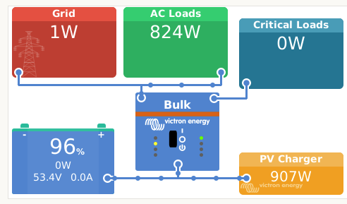
Grid setpoint never worked. Some cells ran away as I tried that many times before, explained why not by @plonkster and @Louisvdw. I tried 0.1a … makes perfect sense re. the reason. Setting Grid Setpoint to zero safest bet. But still a rolling dice.

Therein the charge current with @Louisvdw driver in like ‘lets see what this does …?’ kinda move.

The possibilities now are there, it seems, if cells go outa whack, simply drop the charge current substantially, not the inverter max watts, which is not ideal at all. Tried that too.

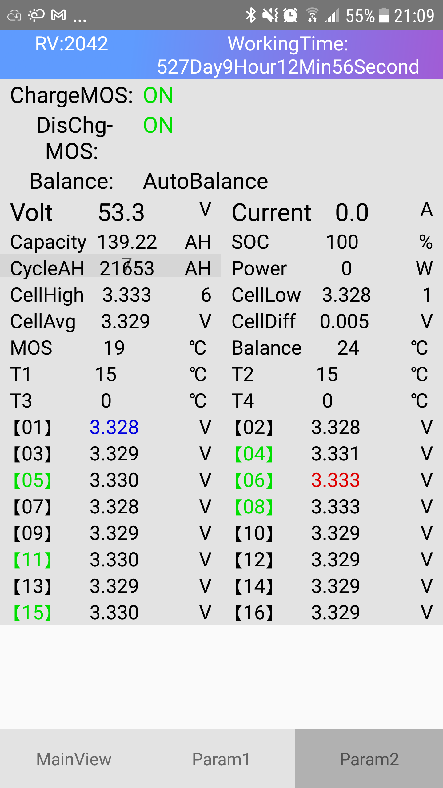
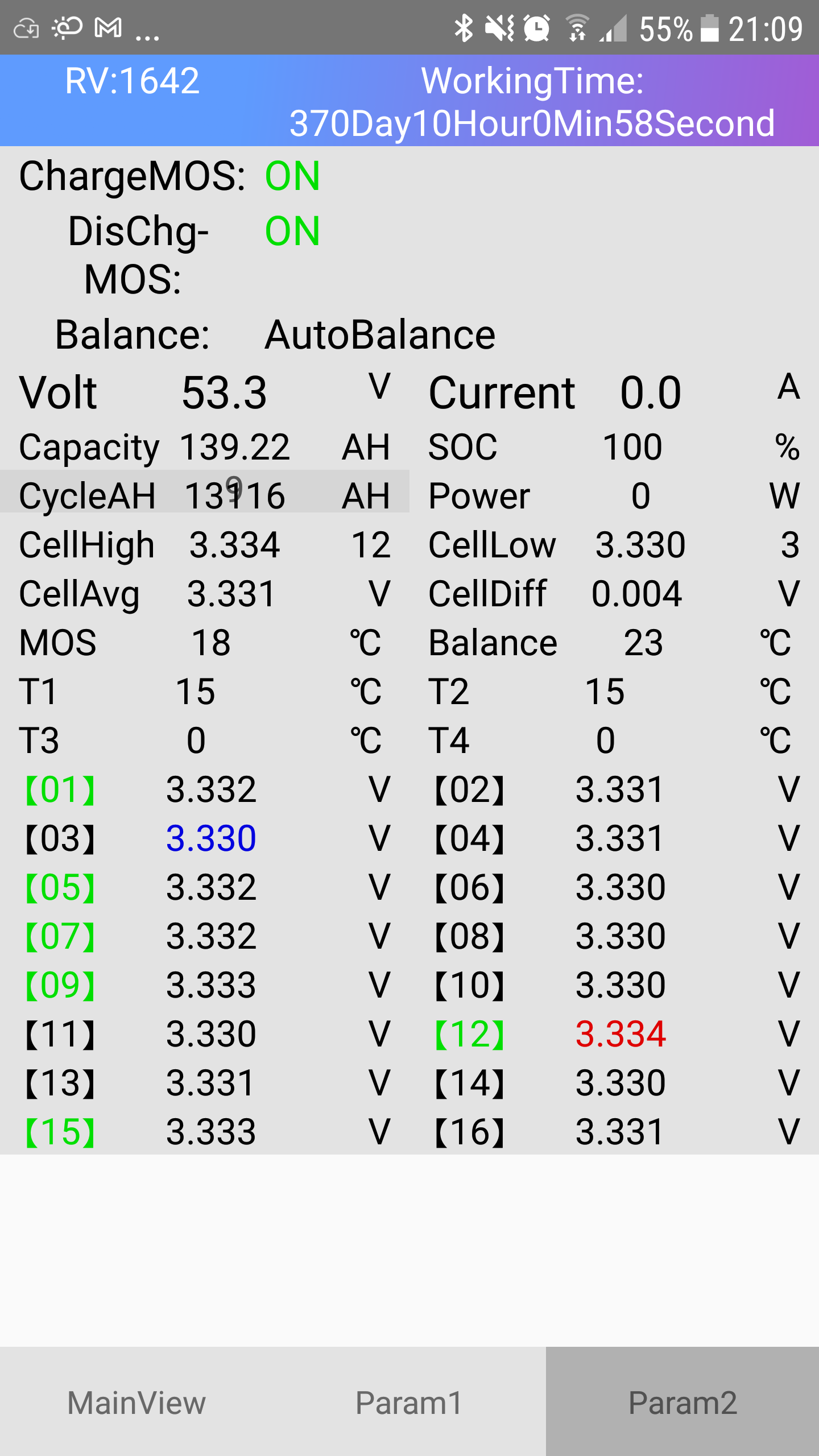
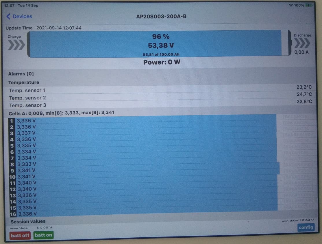
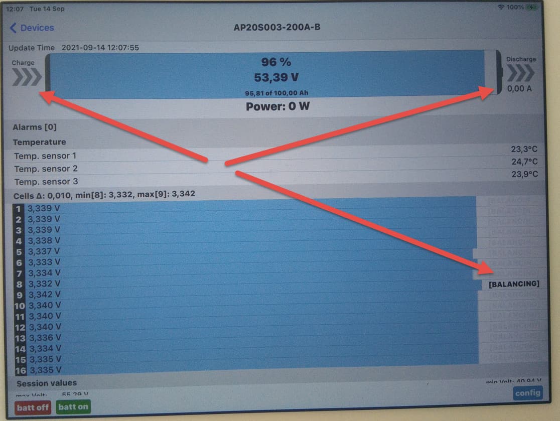
Interesting to note, as long as the cells are >10mv, charge being 0 aka off, balancing still happens until <10mv.

Man, tonight, I am really chaffed!!!

Gonna work the systems a bit … see where the cells are excitable and simply add a couple more settings if needed, like slowing charge at 80 or 85% or whatnot.

This 3.65v fully charged … I have NO confidence a bank will stay like that for 1000’s of cycles. Help the BMS a bit by adjusting to ones usage patterns is my experiences so far. Check where the cells ‘excited’, make the charge amps adjustmentment.

3.45v is my new default balanced production bank max volts.

In other news:
The JBD, I was out, when I got back the relay clicked over and over, cells hitting 3.65v, over and over, The Bulb was needed.

Just one DC Ripple out of 30+ relay opening.

Still need a option for that … Maaaaandag.

Some more info:
On the 280ah cells, they all are min 290ah, I charge them to 290ah on the 12v @ 3.55v with ease … perfectly staying balanced right up to 100% SOC, then to 3.65v starting @ 2 amps to finish them off, on a parallel 16 cell bank.

Takes days.

Next batch @ 3.65v to 290ah 100% SOC in batches of 4 … EV-Peak to finish them off … once.

Then in production the 3.45v again.

If PV is like @ 3900w, battery charge is off, then a 2kw geyser goes off, throttling takes a few seconds, but with no charge to batteries, throttling back seems to take a bit longer than if charge was still on. Does makes sense though.

But what if system was not grid tied, charge being off, where does the 2kw then go, @plonkster ?

What @TheTerribleTriplet doing is correct. I did the same thing for some time now with my setup. On some of the evenings I will drop the inverter down to 4amp charge to supply my 2 lifepo4 banks, so it’s 2 amps per side. The Ant BMS will start balancing when receiving under 10amp of charge. I will leave the setup like this and BMS will do his job and you will se slowly the the volts between the cells leveling out. Like I told TTT in the past, jy moet basies die selle net kielie liggies.

Other thing I like to do is, if we go away for a weekend or a week or so, then I will switch the house over to grid after the batteries is fully charge, switch the setting on the BMS to start balancing and leave it like this.

This is the what I get after leaving the setup for 4 days balancing on it’s own with out any charging going in:

@TheTerribleTriplet I spotted something in the manual. @plonkster Maybe you can give us more info. I see in the manual that the MPPT can run Remote on/off and Programmable relay. Is there a way that we can connect this to the Venus/Cerbo relay input/output and adjust on their settings if the shunt picks up that the volts is going past a set point say like 56v because this bms disconnected and now the MPPT is ramping up the volts to scan for what DC volts it needs to be, that the Venus/Cerbo can remotely switch the MPPT’s off for that time and switch on say after a adjusted time that you program the setup?

Yup. The thing to remember about the Multi is that it has no current measurement device on the DC side (no hall effect, no shunt). It estimates it from the AC values, since it has a current transformer on the input and output, and theoretically the difference between those two, multiplied by some efficiency factor, is the DC side.

That’s why you can’t exactly hit small amounts of current. Also, it controls the charge current into the batteries by adjusting the PWM ratio of the H-bridge switches, and it also fights a bit with the grid voltage: If the grid voltage tends to fluctuate a little, then the battery current also fluctuates a little. That’s fine when you’re charging at 10A or more… but very noticeable when attempting to trickle.

The solar chargers are much better. They have a hall effect sensor (an MPPT cannot live without that) and they know a fair bit better what current they are making.

But to expand on all of this… it doesn’t really matter too much. On every recharge cycle, you do some balancing at the top, until you have a high cell and you have to stop. Then you stop. The imbalance remains, but unless it is a severe imbalance, it’s okay. Tomorrow it goes through another cycle, it spends some more time balancing, it gets a bit closer. It gets there in time, just be patient.

1 Like

I don’t agree that passive balancers don’t work if there is no charging current. I know almost all BMSs won’t do any balancing if they measure no charging current, but if you think about it you are just connecting a resistor across the cell which is too high to bleed off a bit of charge and dump it as heat. In my opinion it doesn’t really matter if there is charging current at the time or not. For the balancer that I made, I just use the cell voltages for deciding whether to balance or not and it works great. Since installing it on my battery it has got all my cells beautifully in line.

You are right! Perhaps I oversimplified it a bit too much. Of course the balancer does work by bleeding off some energy from the high cell. What it cannot do however is put that energy into an adjacent cell. For that it needs a small amount of current to flow. So I concede, yes the balancer does work… but I also insist… not as well as it could :slight_smile:

I must admit I don’t understand this mechanism.

Again, I am probably oversimplifying. A passive balancer has a bunch of resistors sitting over the cells. If the cell goes over a certain threshold, a switch (a FET usually) switches on and allows some current to flow past the cell through the resistor.

The switches may be interleaved (odd/even), or some other mechanism might be in place to avoid a situation where multiple balancers (or all of them!) are on at the same time.

Some current however still flows through the cell. But the important part is that the current that bypasses one cell, does not bypass the one next to it. And so, a small amount of charge is added to the lower cell, while it is not added to his higher neighbour. It isn’t really “transferred” so much, and it isn’t particularly efficient either, since the resistor dissipates some energy in the form of heat.

Also, unlike an active balancer, it cannot transfer the charge directly from the highest cell to the lowest one. If your high cell is cell0, and your low cell is cell15, it’s going to take ages passing charge to neighbours (causing them to be higher again) until it reaches the cell at the end… :slight_smile:

Why do it? Cause it’s cheap, and it kinda works :slight_smile:

1 Like

Here is what I see. Jis I’m still smiling.

System fully charged, the part where I start seriously worrying … the lower the AC watts at these high SOC’s, the words the DC Ripple, from the PAST! :laughing:
image

Now I see this … Grid Setpoint is Zero, no small draining of the batts either …

And very now and then, this, on the iPad sitting in front of my screens, had to wait for this shot:

Dishwasher is on, cloudy day … AGAIN!
image

If the draw drops during the cycles, the difference goes to the gird, not the batts as before … so I pay a few cents more on the PAYG meter, so what.

@plonkster , what do you think about Gman’s idea above?

I’m not sure what problem you are trying to solve. Yes, you can switch the remote control of an MPPT with the relay in the GX device. No, there isn’t existing functionality for this, you’ll have to write your own (probably python) code.

There isn’t really a problem here. If the BMS disconnects the battery, the MPPTs still regulate the voltage as they are instructed to. The DC bus is a bit more bouncy because the battery is disconnected, but also shutting down the solar chargers is not going to make that better, it is going to make it worse in all likelihood. Also, the MPPTs is not going to scan for a max power point… cause it is not in maximum power mode. It is in voltage/current limiting mode (cause it has nowhere to put the energy).

Thanks for the info around this @plonkster . Why I was asking this question is, say the contactor on this BMS opens and there is no battery, then the Shunt or the Cerbo/Venus can pick it up and inform the MPPT to stop with the charge, basically a safety layer we say, and give the bms say a 10min time to recover what it needs to do.

On the other hand this BMS of TTT can speak to the Cerbo/Venus so I guess it will inform the mppt to start backing off on supplying power to the battery/inverter.

Or maybe not? it’s cutting the source of power that is suppling the setup. I just need to add that I’m talking about the battery DC side of the MPPT.

I’m taking a guess because I have seen on my Old setup with the Microcare mppts where if the battery disconnect the mppts will start scanning looking for the battery volts and will go over the 60v then. Microcare solved this now with a new device they install in to the MPPT. This is when I was testing with 56v bulk charge. After seeing this I adjusted back to my old settings of 54.6v and problems.

Other thing why I’m asking is, I bought a 250/100 and 150/100 and Cerbo and Smart shunt and 2x ET112. I’m waiting for my other lifepof4’s to arrive, basically will be running 3 lifepo4 banks that’s 30kwh storage with a 10kw array with the 2 MLT inverts. So it’s a new learning curve for me with the Victron stuff now.

I get it, but you really don’t have to do it. The MPPT will still hold the voltage at precisely the place you told it to. It will provide only as much current as is needed to power things on the DC bus. And you want this. You don’t want the DC bus to drop out and the GX device to lose power.

Also, the Multi also keeps the DC bus powered (but much less accurately than the MPPTs), so even if you cut the MPPTs, the DC bus remains powered as long as the Multi is on.

There is really no point in mechanically stopping a Victron solar charger. It already stops… lest it pushes the voltage to the high heavens :slight_smile: