I’m interested in what I can do to improve the likely lifespan of my two Pylontech US3000 batteries. Note that this doesn’t mean I want to necessarily apply the manufacturer’s specs. My aim is to get the longest possible life out of my batteries together with a practical amount of use. As per a previous post I made, I am concerned that the economics of a large bank doesn’t make sense (in my case, with limited back up requirements). Therefore I’d like to keep the two that I have now in service as long as possible, and therefore enabling my PV and backup system to function as intended.
Picking up a few things here and there (of which not all are necessarily correct), this is a list I put together, but would really appreciate some input on:
Do not use the batteries when they are too hot (how hot is too hot? Above 30C?) or at freezing point (not an issue where I stay).
Avoiding discharging of the batteries at more than 1C (75A per battery in my case, so 150A in total)
Charge them up to 100% regularly (at least once a week) and keep them at that level for an hour or two to do some balancing.
Do not discharge the batteries to less than 20% SoC (80% DoD).
At the moment I am leaving 1 and 2 to the batteries’ BMS to sort out with my Venus GX, so I assume that those are taken care of. For 3, I have put a scheduled charging slot, every day (stop on 20% SoC) between 16:30 and 18:30. My panels are west facing so I still get some sun during that time and the demand in the house isn’t too much, so typically my batteries gets full at around 15:30 and stay there until 18:30, trickling up every now and then with the excess PV, should the batteries demand it.
Another setting I made was to set my minimum SoC (unless the grid fails) at 50%. My reasoning being as follows: 50% DoD gives me 3.5kWh from the batteries. This is at full nominal capacity. When this becomes too little due to capacity degradation, I can move it down to 45% SoC and eventually all the way to 20% SoC. 80% DoD, with 60% nominal capacity remaining, I’d still get (1-0.2)*(0.6)*7 = 3.36kWh from the bank (what I was used to).
I wonder about the regular balancing thing. If the BMS stops individual cells from charging while the others catch up it probably is immaterial but if it continually bleeds off from the high cells then the indivdual high cells will go through more chare/discharge “activity” compared to the neighbours and therefore have a theoretical faster decay than the lower cells… thereby still decreasing overall life.
In a two battery stack it may also not be relevant but if wanting to be totally pedantic I wonder if there is benefit to be had from swapping battery order around now and again?
Yeah that is the reason for my asking. Anything I “know” on this topic is from “hearing” not “understanding”. I do not like basing my actions on something I don’t understand…
What is interesting is the perceived risk/fragility we connect to the lithium batteries and not so much to the other parts of a system. Thinking of the batteries as a consumeable feels wrong but even PV panels will not maintain the original output forever - yet we do not look into UV blocking lotions to prolong panel life (mhmmm note to self … money making scam idenitfied ).
Why are we happy with a R20 000+ inverter without a 10 year warranty but a R20 000 battery must last at least 10 years…
An active balancer has a little isolated DC/DC converter and enough electronic switches so that the input of the converter can be connected to a high cell and the output to a low cell. It then transfers a small amount of charge from the high cell to the low cell. Of course this puts the high cell through small charge/discharge cycles at the top… but I would not worry about it. Highly charged LFP cells hold very little energy in the added voltage, and most of that charge sits fairly “shallow” if I can call it that… the cell hardly feels it on a chemical level.
A passive balancer simple shunts some of the current past the cell (through a resistor). This does not actually discharge the cell, it merely prevents the current from going through the cell and raising the voltage, while still allowing it to pass through the cell next to it. So this is even less of a concern where passive balancing is used.
Passive balancing is way more common. Since most Saffers use Pylontech, which balances passively, there is no need to worry.
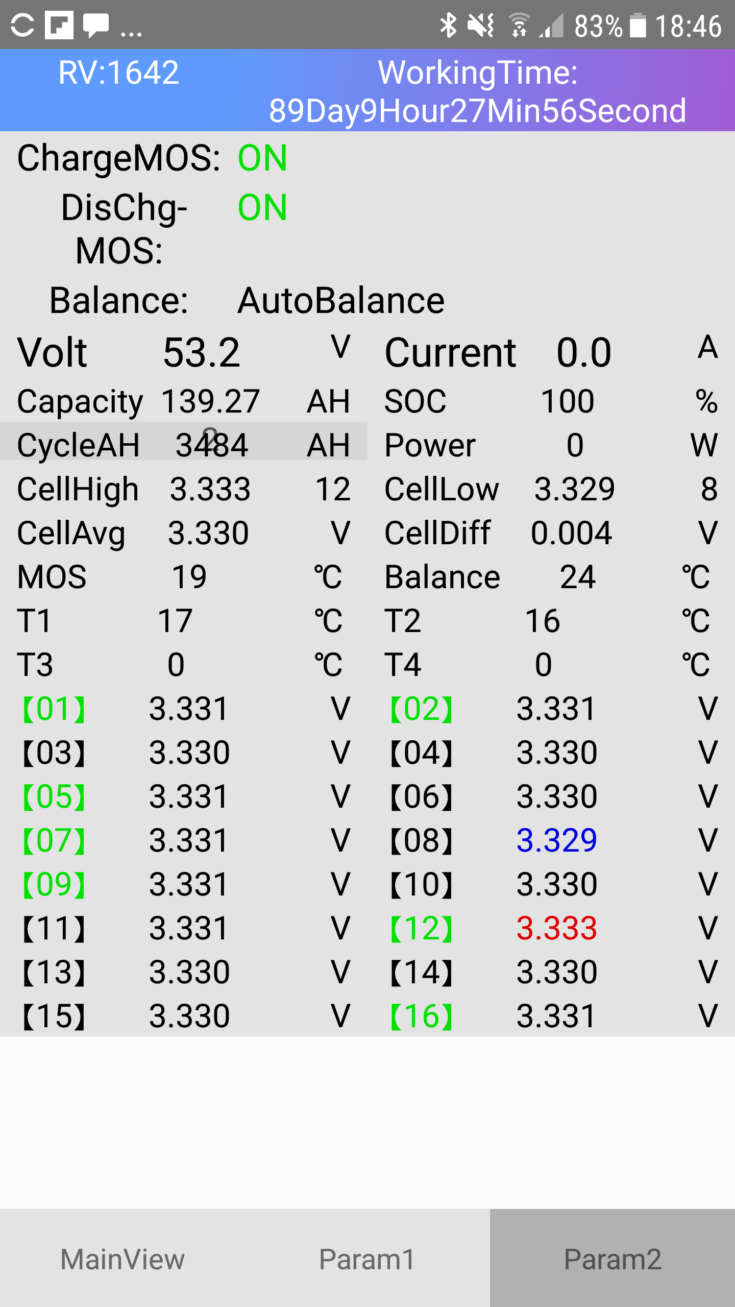
How can you see if a BMS is Active or Passive balancing. Are there a certain circuit you can look for in the one? My BMS can do 50-60mA balancing but it does not state if that is active or passive
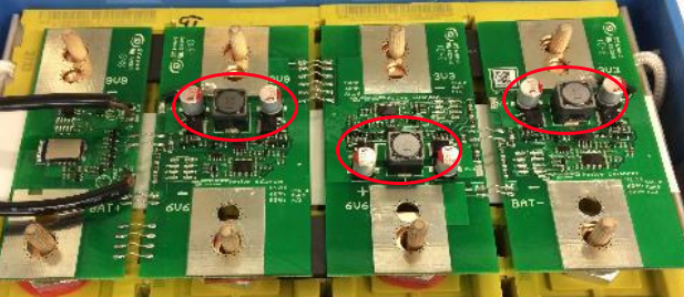
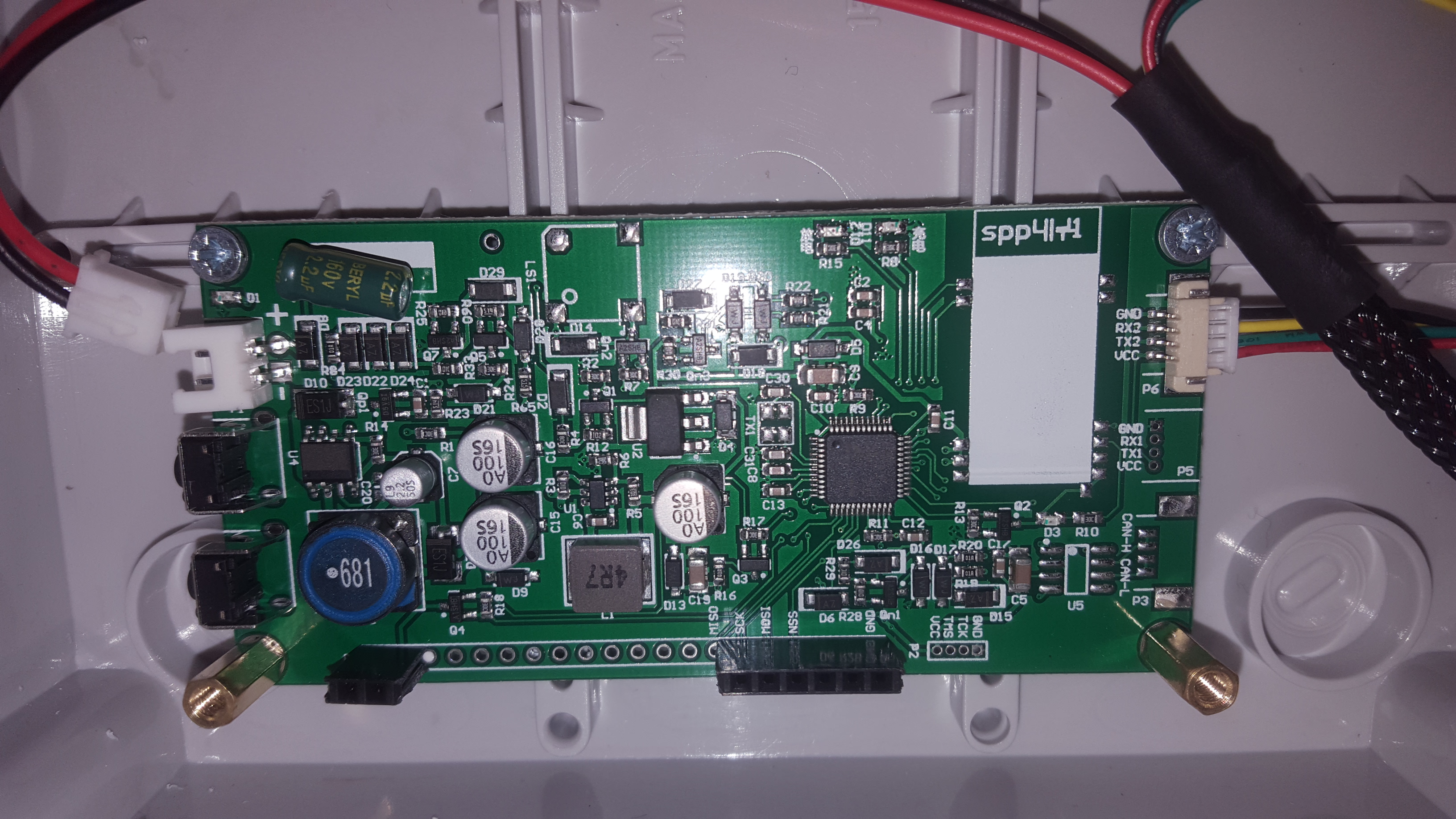
In an active balancer you will see one or more switch mode power supplies. An SMPS will have an inductor. So for example, it might look something like this, SMPS-looking things marked in red:
In a passive balancer, there’s usually a small resistor across each cell with something to switch it. So you will usually see a string of resistors somewhere.
I don’t quite know what to make of the one you posted.
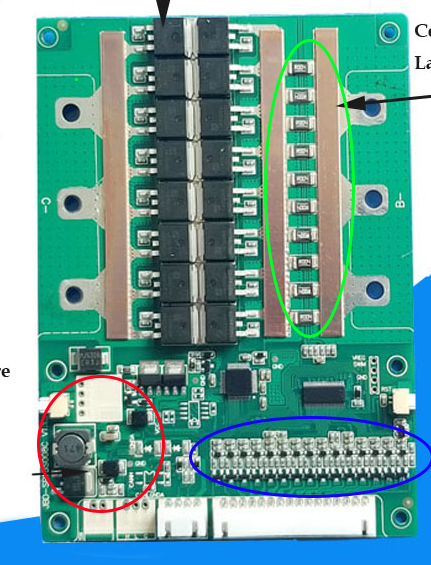
In the red circle, that looks like some kind of SMPS. The inductor is the giveaway. But that may just be the power supply for the board itself (CPU will need 3.3V, etc).
The blue circle appears to have 15 little 3-legged components. Quite possibly 15 small FETs to go in the gaps between 16-cells. But it also looks like there are a number of surface mount resistors across the top end of those FETs. So this would be a passive balancer if I had to guess.
The string of 10 surface-mount resistors in bright green is in fact a shunt (multiple resistors in parallel to create a low-resistance) for measuring current flow. The big FETs between the copper bars are the protection FETs, possibly half of them blocks charging current while the other half blocks discharge current.
The Interesting thing about this BMS that I had to figure out is that you can switch the balancing on/off and then also balancing while charging on/off. If you switch on balance while charging it only balance while charging, and if you switch it off it only balance while not being charged.
When I first got it I switched all the balancing options on and let it sit for a week to balance the batteries and it did nothing. It was because I had the balance while charging option on. A little weird I thought.
Balancing while discharging is usually not a good idea, or so I am told. Apparently there is a natural variation in voltage between cells during discharge. Besides, balancing while discharging is only done with active balancers… unless I have my information completely wrong. As far as I know, a passive balancer balances only while charging, and only once the first cell exceeds a threshold voltage (ie at the top). The trick is to charge slowly (a few amps) from 85% onwards, to give the BMS ample time to balance.
I agree, but seeing as the BMS does not come with a manual this was a bit of a gotcha to figure out through all the settings.
That is what I tried to implement in my driver, but the funky cell in my battery does not want to play ball. I’ve set the charging to <1A and the volatage that of the pack, but that one cell always runs away and then the BMS protects with a disconnects. The rest of the cells all sit at 3.42V or less.
I am starting to wonder if I need to rather replace that cell.
Louis, a option that you can maybe check is to get a lifepo4 charger, like the ones the guys use for hobby cars and planes. Then you charge that cell while it’s still mounted in the pack. I did it with mine. The first pack of 2nd lifes batteries I got I founded that there was some sells that needed a bit more of charge “stupid me, when the pack was standing for 2 months waiting for the BMS, I must have connected them in parallel that they can balance out, I did this with with my second pack of lifepo4s and worked super”. So I got a lifepo4 charger from my one friend and adjusted the amps charge and top up some of the sells. I spotted this weekend that I got one sell again that’s low so i need to top that one up again.
What I actually need to do is, when I got my 3de battery bank up and running, I need to pull the 1ste bank out and stack them parallel and get a bench DC adjustable charge and charge them up.
My problem is that I don’t really want to go too big with the battery. It is a big expense. So there is no plans to add an extra bank. (trying to limit myself with the spending )
I did leave my cells connected in parallel for few weeks before the battery build, but I think they were not charged enough at that stage to really pull at each other. If I had to to this again I will give myself 1 big piece of advice:
“Self, first charge the cells as high as you can, and then go and leave them for 2 weeks connected in parallel to stabilize.”
A little off topic, but it is amazing how concepts change over time. When I last actively worked on this stuff (late 90s), an active balancer was anything that had any sort of intelligent selection of cells to balance. A passive balancer was truly passive - eg a resistive divider, or switched capacitor network, which just provided global charge distribution.
It looks like the original ‘passive balancers’ are now consigned to the history books only, and the term is now used for the simplest form of (what was previously called) active balancer…
Jip. My second bank was standing for just over 3 months waiting for a bms. They were stack in parallel and you will see they close to spot on! The bms i got will do ballancing when there is no charge or discharge. It will do ballancing if there is less then 10amps of charging going in and then it will do ballancing if there is a cell to high. Then it will stop the charging part but the discharge part will stay open.
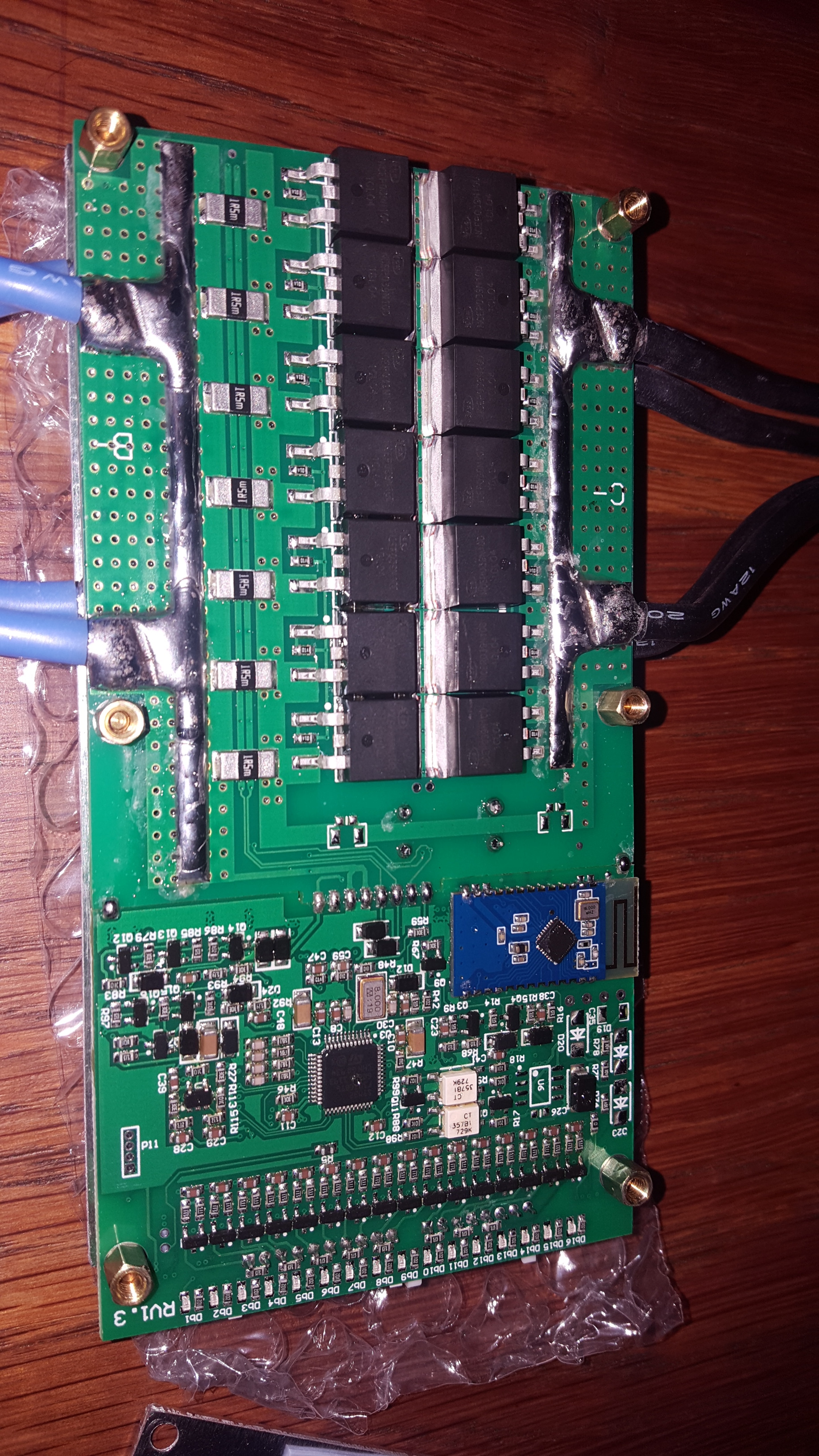
If I compare your pictures with those from my BMS I can see the shunt (green circle) and the small FETs (blue circle), but not the SMPS (red circle) on the ANT BMS
Not much. I see a string of what looks like 16 3-legged things. There are surface-mount resistors on the edge of the board (102 means 1k, 10 with two extra zeroes).
I see many traces going to the right leg of this 3-legged semiconductor. Assuming it is a FET, that would be the “source” (normally the order is GDS, gate on the left, drain in the middle, source on the right). Nothing much to say other than this is likely the resistor/switch ladder for your passive balancer.
Square chip is an STM32. That’s a 32-bit microcontroller, probably the heart of the operation.
Two white opto-couplers. One sits the other way round to the other one, so clearly one is for TX and the other for RX. Those are usually used where galvanic isolation is required. Your guess as good as mine.
My understanding is that most of the damage/degradation of the cells in a battery pack occurs at either end of the charge curve. It is therefore very common for users to limit the use of the cells so they don’t get into the low end of the charge curve, i.e. don’t take the pack below 10-20% SOC. However it appears that not many people worry about keeping their cells from fully charging.
If I wanted to extract the maximum life out of a pack of cells I would not take them below 20% SOC or above 80% SOC. That would give you 60% of the capacity of the cell pack. You could then extend how much of the charge curve you use as the battery ages in order to maintain the capacity you want.