So, my inverter’s switchover time hasn’t been an issue for any device in my house. However, this morning when the power went off, I noticed that my LED dimmers pick up the transfer time as a “click” and because they aren’t “on” or “off”, you click the button once to make it change state (go on or go off) or hold the button down to dim, they register the transfer time as a “click”.
This is going to be exceptionally irritating to me and I was wondering whether anyone has a solution? These are all new dimmers my contractor’s electrician installed and this is now the first bit of loadshedding we go into with them in place, which is why I haven’t had issues until now.
Our bedroom ceiling lamp comes on briefly (twice) when the power returns. Well, by “come on” I mean it glows faintly, but it is very apparent at midnight if you had a 10PM-12AM outage, and you happen to still be awake.
Which is quite interesting, if not as irritating as your problem.
It clearly has to do with the action of the bonding relay. When the power returns, the inverter does a relay test (which briefly disconnects the TN bond). Then it waits 60 seconds, and then it connects to the grid (which again sees a brief disconnection of the TN bond). As we all know, removing the TN bond causes the supply to float on either side of earth, causing around a 100V or so between neutral and earth. I suspect this (LED) lamp has a filter of some sort inside, which some of this voltage to be conducted to the live side of the lamp (probably forming some kind of voltage divider across the filter), and the small amount of voltage that shows up like this is enough to make the lamp glow briefly.
So there I was shortly after midnight, explaining to the wife that there is no reason to worry about that. It’s just electricity being weird.
I’m starting to think that my problem will be better to solve with these dimmers:
Then there’s a physical switch to ensure power runs to the lights and a rotary dimmer to determine the current. Though, these are LED lights I have to presumably the dimming is done through PWM?
As far as I understand, from speaking to a dimmer manufacturer. The dimmer has a 5V supply referenced to Live. The button connects live to one of the pins on the microcontroller. So when the button is not pressed, the input is low (Live -5V which sounds a bit odd since being AC, live is both positive and negative relative to neutral, but anyway that was his explanation) and when the input is pulled to live, it is detected as a button press. Unfortunately a glitch in the AC waveform can cause the microcontroller to detect a button press. On thing that was suggested was to put a capacitor across the button, or an LC filter on the AC supply to the dimmer.
Ah this makes sense (as much as it should make sense to a layperson like me). This makes me think that it needs some type of “debounce” circuitry. But I’m going to see if I can’t do away with these “electronic” dimmers and rather get the physical one I posted above. I’m sure those would work?
Yes, of course a dimmer with a physical on/off switch would be immune to this problem.
Great, then that is what I get. I’ve always found analog solutions to be the most reliable.  Obviously this isn’t the best when trying to make your home “smart”, but I’ve got no intention of putting my lights on Home Assistant.
Good idea. Keep dimmers and home automation away from each other. I know of somebody who has some obscure home automation system and dimmers. When there is a changeover, the dimmers register a ‘zero crossing fault’ and turn off. The only way to turn them on again is to clear the faults first. It’s a pain, and the dimmer’s can’t be replaced because those are the only ones that work with that particular home automation system, which isn’t made anymore because the company that made it no-longer exists.
Ah, which is why I tell everybody who wants to get into home automation the same thing: This isn’t something you get someone to do for you. It is something you do yourself. One day, something will go whack, and you need to be able to fix it or bypass it.
Ideally everybody would be able to do their own home automation, but unfortunately most people just aren’t capable of doing it themselves and if they have enough money it’s easier to just pay somebody to do it for them.
They refer to ‘trailing edge’ (which references the AC of the voltage after the sine wave peak) This means they aren’t using PWM to control the voltage.
PWM is used on DC circuits and since you have LED lighting this would be ideal. But this would mean that the wiring from the dimmer to the LED fittings is not AC (not that the triac controllers are a beautiful sine wave either)
You get both Leading edge and trailing edge dimmers. This refers to how they ‘chop’ the waveform. Leading edge dimmers are off at the beginning of the half-cycle and turn on at some point depending on how bright or dim you want the lights. These typically use thyristors or triacs (same thing). Trailing edge dimmers on the other hand turn on at the beginning of the cycle and then turn off after some delay. These typically use FETs.
Somewhat unrelated, but I’ve found that these dimmers have a faint flicker. Not too noticeable, but not as comfortable as normal incandescent or halogen dimmers. Is this just a “feature” of LED dimming? My electrician used dimmable LEDs from the same supplier as the dimmers, apparently tested and which should work together.
All I can tell you is that LED lamps need to support dimming… or it simply won’t work. The non-dimmable kind has a switch mode power supply in the back that takes whatever comes in (down to as little as 90V or so) and changes that into a suitable DC voltage for the LEDs to run. If you put an ordinary TRIAC-type dimmer on it, the incoming energy is reduced on the AC side, but the SMPS in the LED lamp simply compensates for it and passes a larger part of that to the low voltage side. So the lamp doesn’t dim at all.
The effect of this is a lamp that doesn’t dim until you have the dimmer turned almost all the way to the bottom. At this point, the energy becomes too low for the SMPS to power the LEDs and the lamp starts flickering or simply dies.
So normally you cannot use the same dimmers for LEDs that you use for halogens, and you cannot use non-dimmable LEDs at all.
Dimmable LEDs use some kind of PWM. Traditional dimmers chop the leading/trailing edge of the waveform.
To be honest, I have no idea how modern dimmable LEDs work. Only that they don’t work like you would expect. So you probably cannot buy just any hardware store dimmer and expect it to work.
Slight flickering could be a dimmer issue (the turn on / off time varies slightly from one cycle to the next) (this could be caused by the AC supply if, for example, the frequency is a bit unstable) or it could be the LEDs themselves. I have seen dimmable LEDs that flicker at certain different brightness levels because they turn the LEDs on in groups, so that when very dim only a couple of LEDs are on and then as you turn up the brightness, more turn on. Unfortunately you could find a few spots where a group of LEDs would constantly turn on and off causing a flicker.
1 Like
Surely when you dim using PWM flicker would have to occur because it literally turns on and off very quickly? The flicker is much more noticeable when the LEDs are turned “dim” vs. “bright”. On bright the flicker is basically gone.
That is usually the case. I think it’s because slight variations in brightness are more noticeable when the light is dimmer. The PWM or chopping shouldn’t cause flicker due to the on-off behavior, since normal lights flicker at 100Hz due to being supplied by AC and you don’t notice it. Dimmable LEDs usually have some sort of power supply which rectifies the incoming AC and filters it to get a fairly smooth DC, which should reduce flicker. I guess it really depends how the LED controller DIMS the LEDs and how well the dimmer can make sure that each cycle is exactly the same.
But surely normal lights (incandescent) has some “capacitance” to them for you to not really notice the grid’s frequency?
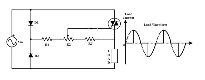
This is a typical dimming circuit using a triac
It delays the switching on of the AC waveform and the resulting waveform is the remaining AC voltage.
This was the way dimmers were made with thyristors and triacs since they were the first semiconductors that could switch AC.
1 Like
Yup, and this chops the leading edge. Cannot chop the trailing edge since the thyristor/triac only switches off at the zero crossing. So trailing-edge dimmers use other components so they can switch off in the middle and leave the trailing edge off.
As far as I know the main reason for doing trailing edge is to reduce radio noise. But I could well be wrong. And I still don’t know anything about how dimmable LEDs work 