This is a repost from a thread I created over a year ago on another forum. As I never visit there anymore I wanted to move my content here. Sorry if this is a double post for some of you.
Over the last several months I have been installing my inverter system bit by bit. Here is my progress (written as a bit of a guide if it helps someone else).
Planning
My goals are:
- Have UPS power
- Offset the cost a bit by adding solar
- Stay within my limited budget.
- Be modular for “add-as-you-go” option
I don’t want to go off grid - that is just too expensive. So I can install a smaller inverter.
As I will be doing most of the work myself I wanted something that has very good support and documentation. The natural choice for me was a Victron system.
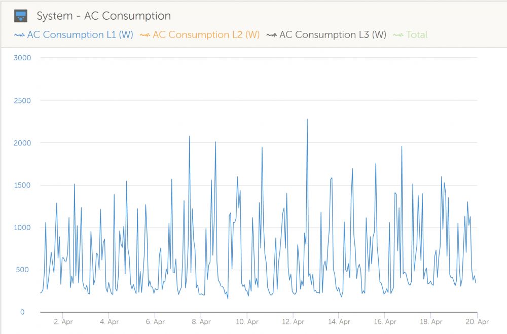
I started off by finding my usage patterns(when) and consumption(how much).
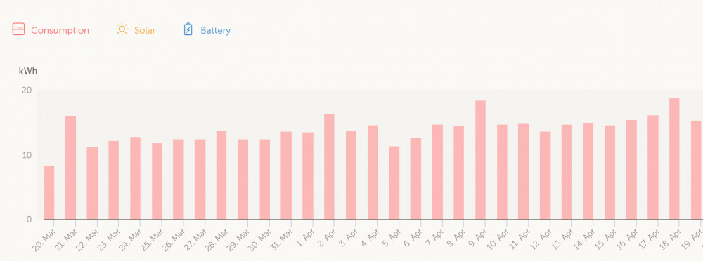
The easiest option was to use the Victron VRM cloud. I already had a Raspberry Pi3 that could be used for this purpose, so all that I needed to do was to install the open source VenusOS using the steps from here. (the other option is to buy 'n VenusGX device that already have all the required inputs/outputs). Leave it to get some stats over a month (or 3 if it is lockdown).
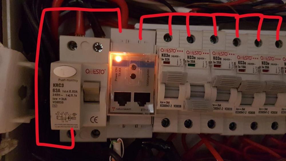
The ET112 energy meter (about R1100) is a good option to hook up into my DB. You install the meter between the earth leakage and the the rest of breakers.
You also need a 3 wire cable (4core security cable or 6core network cable will work fine) and a RS485 USB converter like this one to make the meter talk to the Pi3. The negative(blue wire) go to terminal 6 of the ET112, and the Data A & B goes to terminals 4 &5.

Batteries
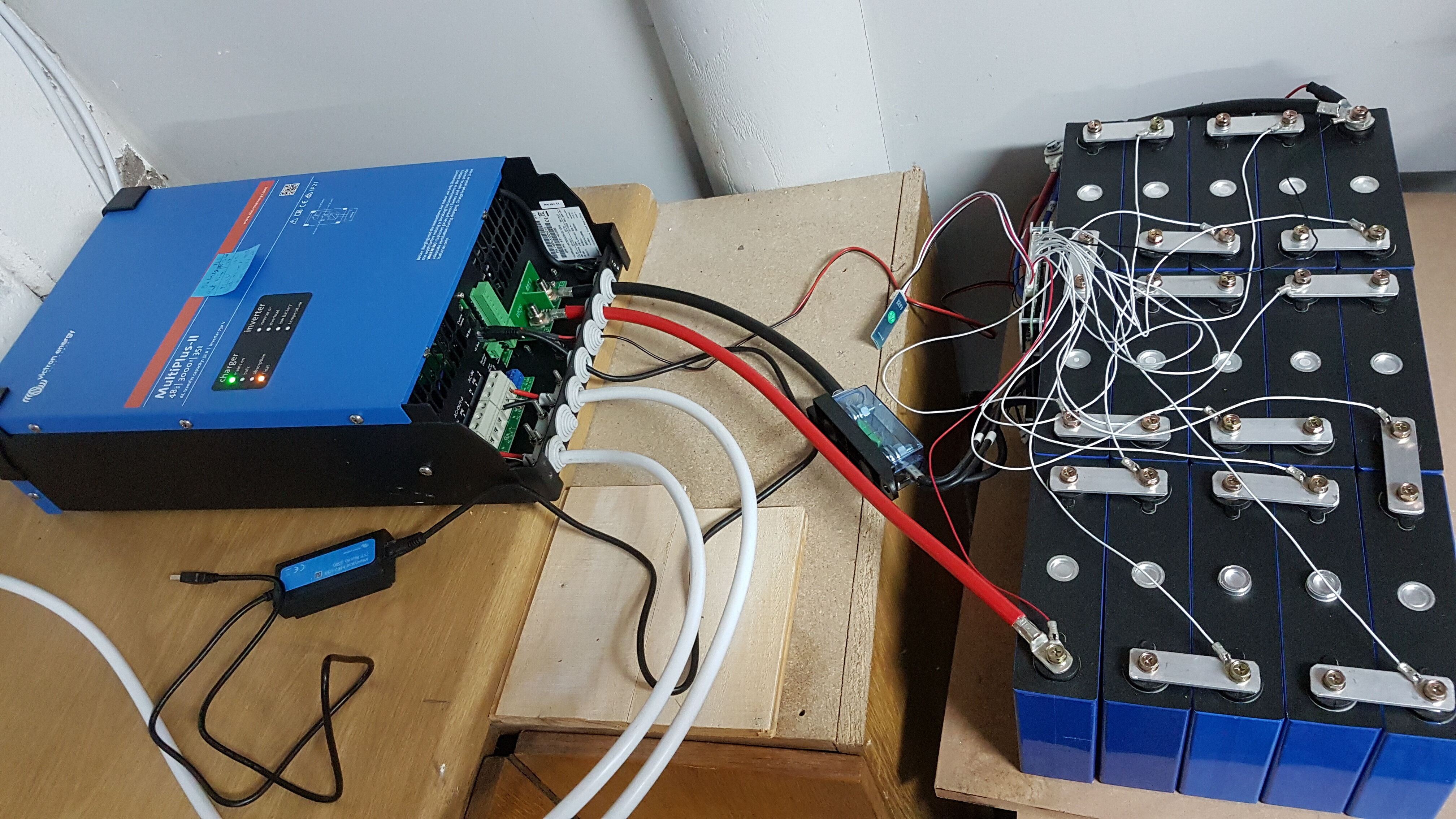
For batteries I decided to build my own using a LiFePO4 cells(4kWh) and a smart BMS.
The 15S 100A BMS was ordered from AliExpress and arrived just after the first loackdown lifted, and the cells came from a mismatch special from Sinetech. I created cell connectors from 3mm aluminium bar and connected all the cells in parallel few 3 weeks to equalize. The smart BMS also has a cell balance option, and that helped a lot to get the cells in shape and on the same charge state. There is a 125A mega fuse on the 35mm2 cable to the battery. All the settings on the battery is set using the bluetooth app on your phone that also includes all the battery stats.
And built a battery case

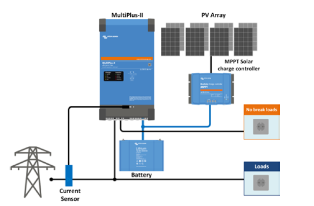
Inverter
Finding that our normal usage is around the 2000W a Multiplus II 3000/48 was the inverter of choice. All the peaks can be handled by the utilities, and if there are loadshedding the stove and kettle will not be in use.
For connection to the Pi3 a MK3-USB cable is used.
I used 4mm2 surfix wire to connect the DB to the inverter, and another 4mm2 wire for the return. There is a 63A change over switch to bypass the inverter (this is to keep the wife happy while I fiddle). For a month or so I just had the inverter and batteries running on the workbench hooked into to DB. Worked well for the first set of post lockdown loadshedding.
Solar panels
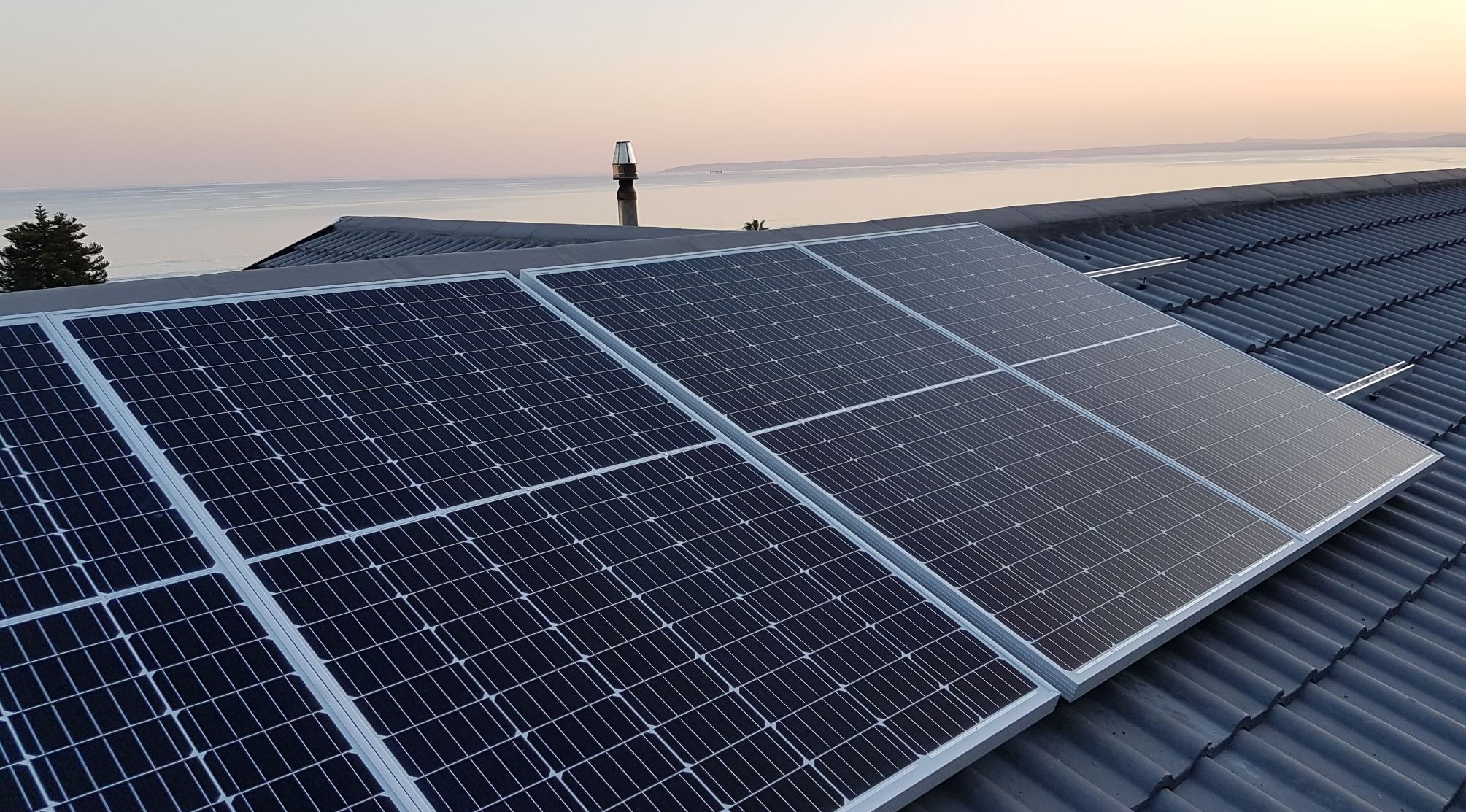
I installed 4x 335W ArtSolar panels using SolarStrut bar and PowAR snap clips.
They are set up 2S 2P using 6mm2 solar cable and 16A Ceramic DC fuses for each cable and a DC breaker between the panels and the charge controller.
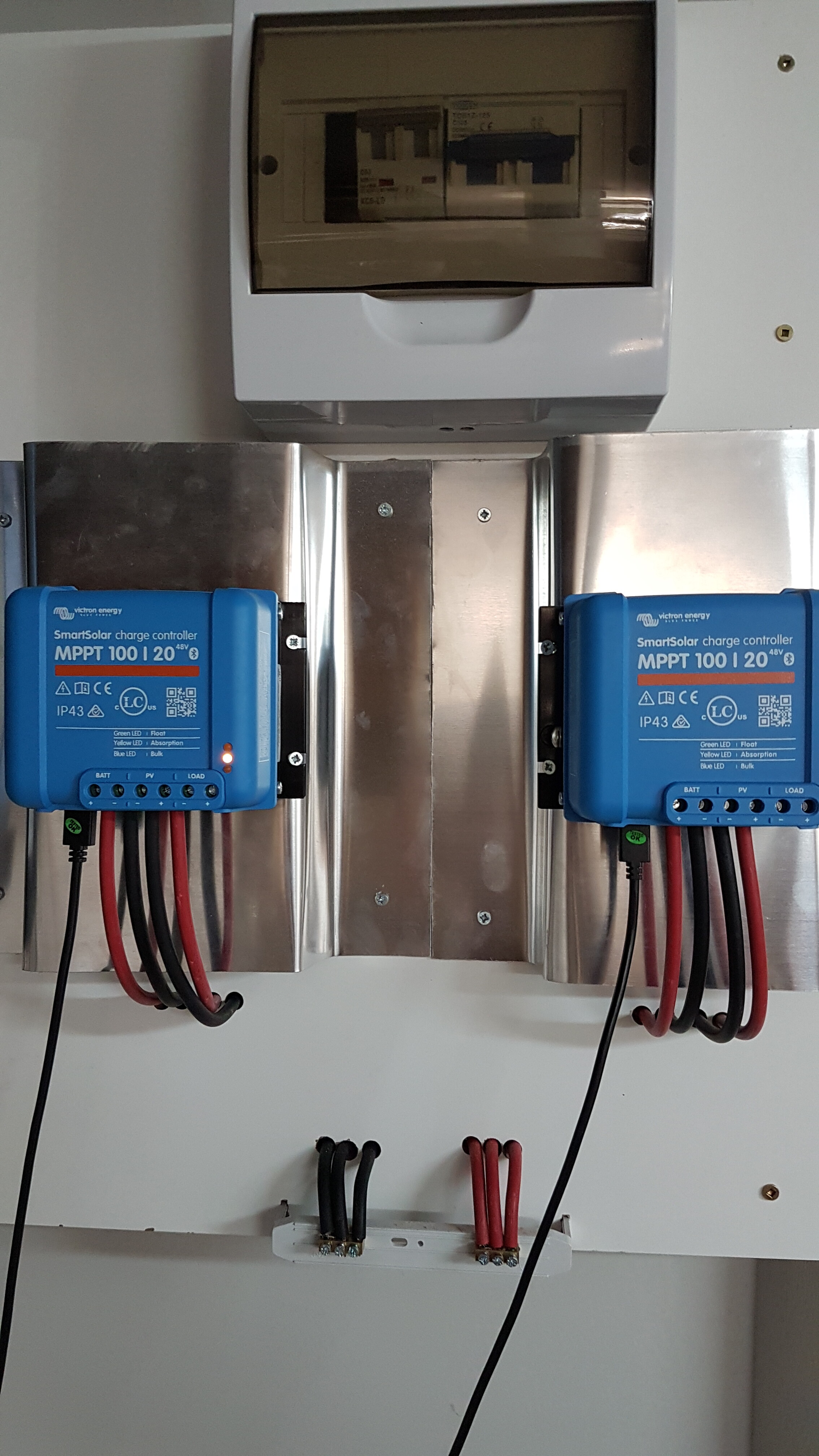
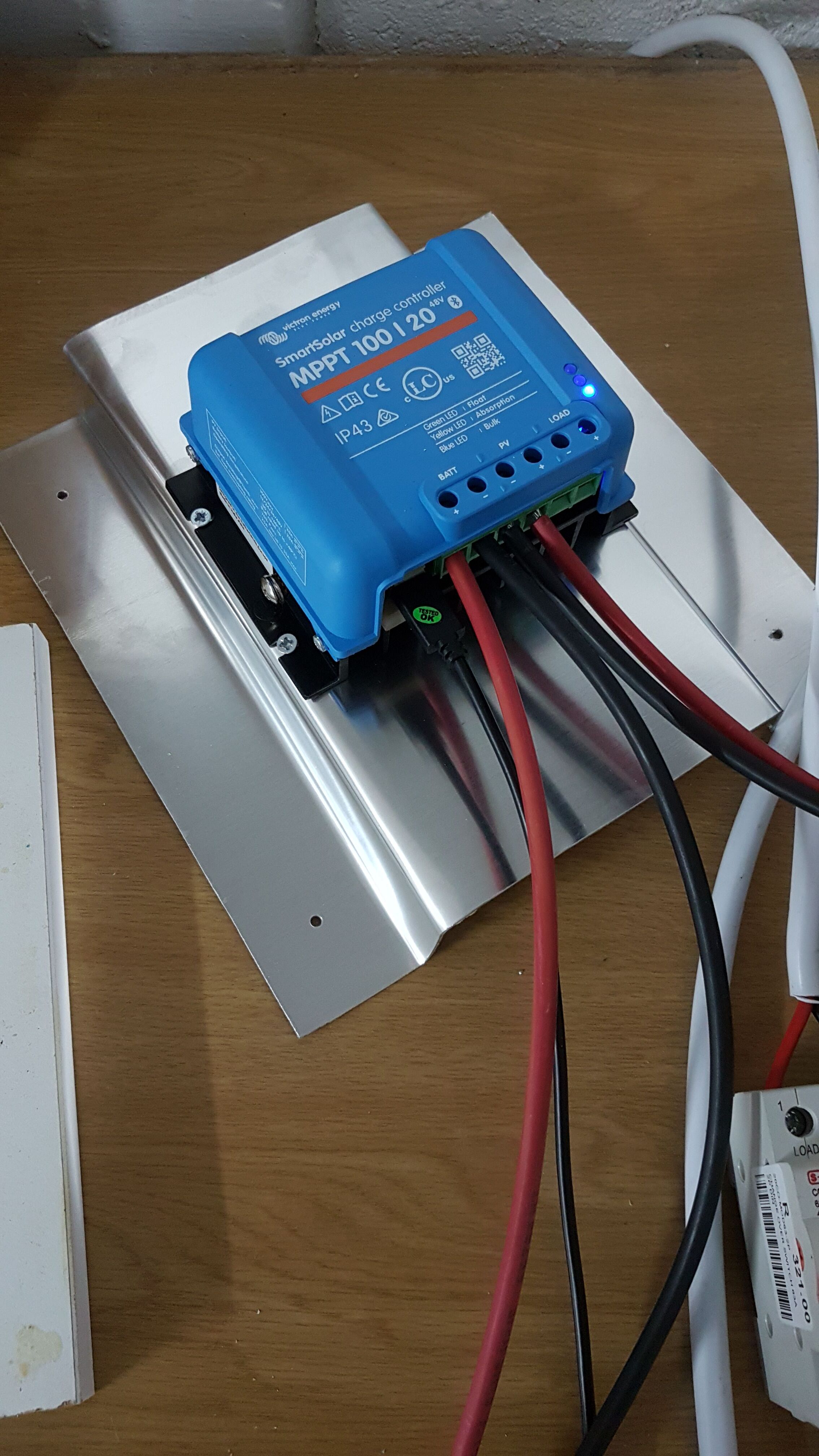
And using a 100-20 (48V) SmartSolar charge controller. I created a bit of extra heat sink to help with the heat dissipation.
The SmartSolar controller is connected to the Pi3 with a VE.Direct to USB cable.
Final Mounting
All up on the wall. I still need to clean up the wires a bit.

I also tackled by DB. It was on the todo list to cleanup and install a bigger box since before the lockdown when I added the ET112 meter.
If anyone has done some fishing you would know a “kraaines”. The 12 place DB could only fit 8 in slots of CB and when I added the double slot ET112 meter push wires into all the corners to make space. Here is my “kraaines” being taken apart. No way to know which neutral and live goes together.
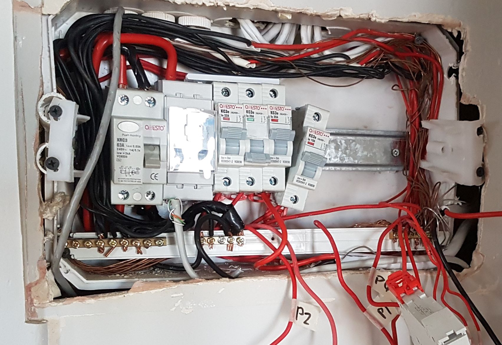
It was a full day of work! Every person turning the corner would have a comment like “Spagetti!” “Spiderweb” or “Is it going to work” 

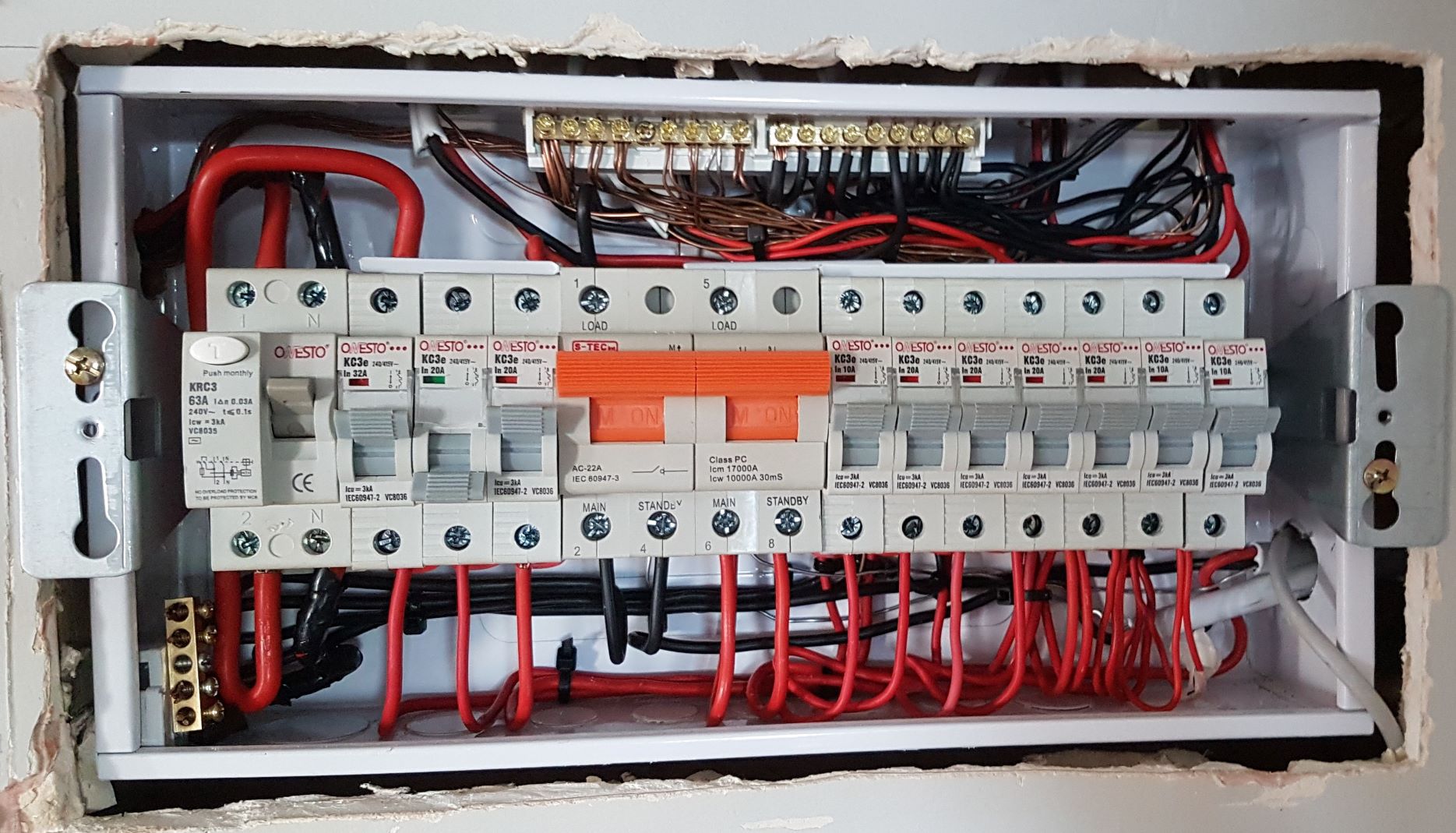
In the end I finished 5:20pm. (made it just in time for the braai  ) Much nicer now and my change over switch actually fit inside the DB.
I also later added a second MPPT with 4 more PV panels.
Each MPPT deliver 1kW power (20A x ~51V for the batteries)