OK, I did the footwork and went looking for the original info. On the ET112 there is already a built-in resistor. Simply connected terminal 3 to terminal 5 to enable termination. No external resistor needed.
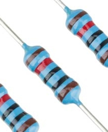
On the USB side, you will have to put this resistor across the orange and yellow wires at the point where you’re extending it. This is what a 120Ω resistor looks like:
The colours will either be brown-red-brown (usually with a 4th gold stripe), or it will be brown-red-black-black if it is a 5-stripe unit (usually with a brown 5th stripe).
You can google resistor coding if you want but basically the very last stripe is the tolerance (gold is 5%, brown is 1%), and the rest is the actual value of the resistor.
The second-last stripe (before the tolerance band) is the number of zeroes at the end. The rest of them spell the resistance. Brown is 1, Red is 2, Black is zero.
So Brown, Red, Black, Black is the same as Brown, Red, Brown
You’d solder this across the yellow and orange wires, with the leads suitable shortened and heat-shrinked down.
With all that said… even at 30 meters, chances are you don’t need to terminate it at all. If the propagation delay is much less than the width of one data bit, termination is not needed and is often skipped for ease of installation or to avoid adding a load to the bus. At 9600 baud… the width of one data bit is so wide that you’re only going to run into problems somewhere on the other side of 100 meters. The adding of terminators is just for peace of mind really.
There is a built-in resistor on the USB side too. It’s on the green and brown wires.
The instructions are to use yellow, orange and black. Just (additionally) connect yellow and green together, and orange and brown together where you make the splice. That’s all that is needed to terminate it. No need to go hunt down 120Ω resistors…
The guys that installed my ET112 and connected it with the Venus extended it with cat6 cable. So basically put the cat6 in on the the ET112, solder and shrink the other end of the cat6 in my garage (about 30m away) unto the USB. Plugged the USB in, works.
I have laid the Cat6 ethernet cable from the garage into the house to the main db and I have spliced/joined same with the RS485 to USB interface cable.
Judging by the route I followed, it seems that the total cable length utilized will be only about 23m
Of some concern is the following mentioned on the Victron wiring diagram:
“To ensure signal integrity and robust operation, particularly ensure that the original cable attached to the Victron RS485 to USB interface is reduced to a maximum length of 20cm in installations where the total cable length is over 10m”
How crucial is this and why would they say this and manufacture this cable up to 5 meters???
“The instructions are to use yellow, orange and black. Just (additionally) connect yellow and green together, and orange and brown together where you make the splice. That’s all that is needed to terminate it”
Vervlaks tog. Hopelik het ek die resistors nie nodig nie.
Morning all. Its been a hectic week and didn’t get chance to spend some time here, but I can now report back.
My sparky after 2,5 weeks still couldn’t find the time to assist with wiring in the Carlo, so I decided I will have a crack it myself. The db was open during this entire time, so every now and again when I walked past it, I would stop and spend a few minutes there to try and make sense of everything in terms of what must be done.
This is how I figure things out and why diy’ing takes thrice as long for me, not being blessed with a 3 dimensional brain lol.
So yesterday without any sparks flying, I managed to install it, and wire it up. After some words of advice and good luck from Jaco De Jongh I finally made the last connection this morning which is the usb plug on the Venus’s side.
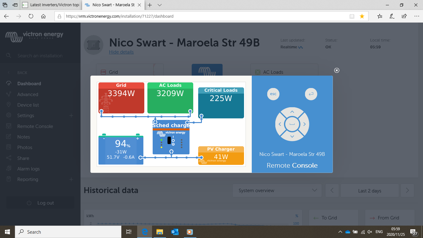
And this is the result. I now have an extra little block that magically appeared!
I suppose the MPPT will now start earning its keep. It has been lazying about sitting idle doing very little hahahaha.
I think I’m going to overwork the poor thing now. Almost ready for my first test. Dishwasher to be started soon. Just waiting for all panels to have proper sun on them.
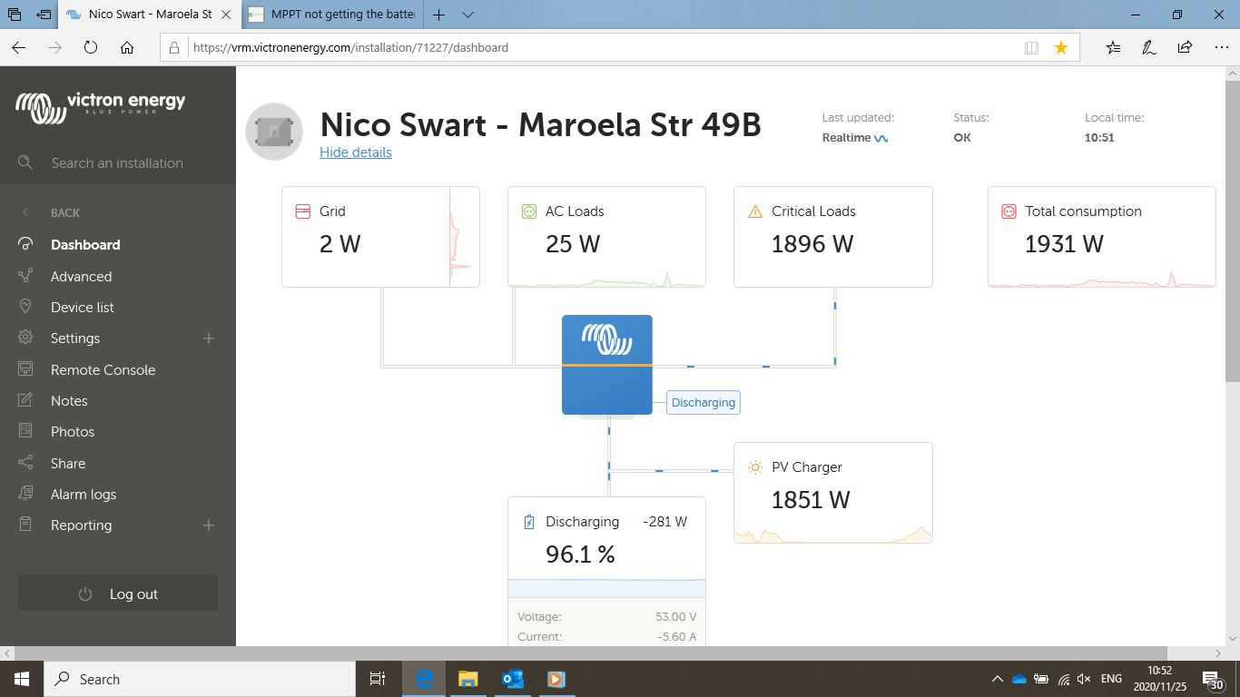
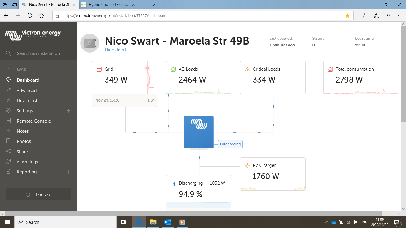
In theory I have a 2,4 Kw array, but not getting there. Is this the deration happening here possibly? It really isn’t hot in the garage currently where the inverter is located.
Depending on the time of day and the orientation of your panels, you will not get your peak. I have 18*320W = 5.76kW (9 West on one MPPT and 6 North and 3 West on another). I peak around 4.8kW.
Mmm still have to find my system’s peak. I know for a fact that some of my panel’s orientation is not optimal. I had to move one string of the three to the other side of the roof on a slightly different angle. So my losses today was then around 0.6Kw which I then suppose is ok-ish.
But this is to catch the morning sun earlier. This arrangement will change early next year when I’m able to put another 2,4Kw on a different MPPT. Then respectively, the panels in both sets will be aligned identical.
From my experience, the peak shifts a bit as the sun’s path change, but at the moment I think my North panels peak around 11:00 to 12:00, and West 13:00 to 14:00. But this is my “feeling”. I haven’t had the chance to run it full tilt the whole day to have a look. Don’t have a large battery bank.
I think you can assume around 80% of losses on generation to be “safe”, and not disappointed. Also moisture etc. in the air might mess with it. Also excessive heat might lower their efficiency. And on cloudy days you can expect to see some massive spikes. Like way over the maximum output of the panels. I’ve seen bursts of upwards of 125% of rated maximum.
More panels are not going to help. You are already getting the max out of your MPPT at 1851W.
Here is how it works:
You have a 150 | 35 MPPT which means it can do up to 35A. That is 35A on the battery side.
Say your AGM batteries are currently at 54V, that would give you 54x35 = 1890W that the MPPT can give you. Pretty close to your 1851W in this picture (If you check your battery volts would have been around 52.88V at that stage)