If the combined loads remains under 32Amps, while grid is available, nothing will go wrong.
1 Like
Yep, the highest combined load was around 5000W and if I am not mistaken 32A = 7360W.
I’m struggling to understand what you describe you did.
Clould you please clarify for me?
Are you saying you connected all household loads on AC1 Out and only from thereon you’ve split some of them to Ac2 Out?
Sorry, I’d really like to understand what you did.
Basically it means that my main incoming supply from the municipality goes into the Multiplus AC-In and from there I put all my heavy non-essential loads (Oven, Laundry, Air-con) onto AC-Out2, and essential loads (Lights, fridges, Tv etc.) onto AC-Out1. AC-Out 1 and 2 have there own DB,s.
ESS then diverts all excess solar power onto AC-Out2 so that during the day the whole house runs off the solar panels. If there is a power failure then only my essential loads are powered from the inverter.
Where I “wrote off” the idea to use AC_Out2 ever, rather use a Carlo as it is simpler, let me ask again for either a “re-think” or “I’m still on the right track”. (for me)
The BIG question: What is the absolute max that a 3kva and a 5kva can handle if both AC_Out1 and 2 are used, and for how long?
And with temp derating, any impact?
“Question 2 - for clarification:” I presume that if one has a changeover switch, you would have one that will swich back the AC_In1?
And not like some do now, just the AC_Out1 DB back to main DB.
Ok I’m with you. This is what I would have done, had not been for the fact that I would’ve had to lay another 4core 10mm2 armor cable over 30m
But I think I get what TTT is saying. You say your family is trained to use one heavy consumer at a time. With my circumstances it won’t work as I would have to train several other people that also very often frequents are house and assist in the kitchen. Not so sure the 3Kva would like being consistently mistreated.
Would like some further views on TTT statement below also.
3kva can do 32 amp pass through plus it’s own rating constantly. The 5kva can do 50 amp pass through plus it’s own rating constantly.
There is absolutely no difference in how hard the unit works by adding its full capacity from the DC side to the AC loads, whether the loads are connected to AC out 1, AC Out 2 or to the input side by using a Carlo. It can only add its own rating to the loads and adding it to any of those takes the same effort.
Derating will not be affected by the pass through loads. As it’s takes absolutely no effort to pass through. The unit does not work harder to pass through 30 amps compared to passing through 10 amps as the units is not generating that 30 amps, it’s merely passing it through and the grid carries the load.
The unit will however derate when you convert the full capacity on a hot day, it will heat up and derate. In short there is a difference in converting 1 Kva VS converting 3kva on a hot day and that will result in the unit Derating because of internal heat.
It’s easy to confuse the effect of passing big loads through and generating enough to power big loads. The secret lies in limiting the loads on Acout 1 to not exceed the rating of the inverter when the grid is off.
2 Likes
@Swartkat
I also have the MultiPlus II 3kVA (MP II) and the ET112 Carlo meter. Let me try and explain.
With the MP II you put all your loads you want to still work when the grid is down on AC OUT1. So AC OUT1 will supply battery backup to those when the power is down, and they will also be powered from the solar panels when there are enough sun power.
The rest of the loads will be off when the grid fails (like your geyser and stove), but they can still be powered from the sun if there is enough solar power available.
The MP II has 2 options for this:
- Power the rest of the house from the AC OUT2 (extra cable back to DB, 32A limit (7000W) on top of any Inverter power (±2400W), so up to a max of 10kW, but I will stick to the 32A as a max)
- Or the MP II can push the power back up through AC IN1 (using input cable, but also need ET112 in the DB and data cable between DB and GX device)
If you use AC OUT2 option 1) then the cable is more expensive, but it is the less complicated option. The MP II also react faster so if you have a problematic prepaid meter this option will give you less problems. I’m currently running it this way, after removing my ET112.
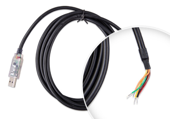
If you choose the ET112 option then you need a long data cable. The USB to RS485 cable that Victron sells only come in 1.8m or 5m lengths, so you need to connect a longer cable to that to make it longer. This connection is called splicing, where each wire in the cable is connected to the extension cable wires and isolating it.
In the old days when people still had to mow their own lawns and you drove the lawnmover over the power cable and you had to fix it before your dads sees what you have done 
The RS485 can go over 1000m and if you do a good connection you should not have any problems on 30m
This is the cable. The USB part plug into your Venus GX device. The red/black is for power and the yellow/orange are the 2 data lines. A Cat5/6 UTP network cable work well for this. There will be 3 pairs (6 wires) in the cable so you can use the one pair for the power and the other for the data wires.
Then use the wire connections from the ET112 manual to connect to the ET112 meter. The Venus should pick up the meter and use it by default.
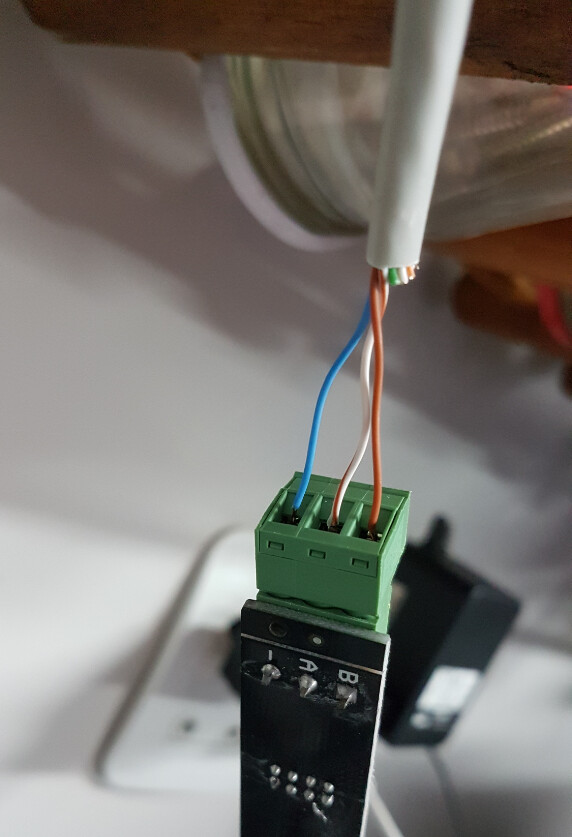
You will see in the picture below the network cable I used for RS485. The blue is the ground from the power and the brown/white-bround are the data wires. You’ll do something similar
Edit: Oops, I had my AC OUT 1 & 2 swopped around
Thanks Jaco.
So IF, and I don’t always do, but I do get there evenutually, understand it correctly, the:
3kva can do 32 amp pass through x 230v = 7 360w
5kva can do 50 amp pass through x 230v = 11 500w
So what happens if say on a 3kva, the house draws 10kw?
You know, those days when the “langhaar huisdiere” decide today is the day to clean the entrie house top to bottom - and yes, you will clean out that garage too - whilst they cook and bake same time?
Post removed by poster … it never happened.
Yes ![]()
You read faster that my edit was
1 Like
Thank you Louis! marvelously well written so that even an id10t like me can understand it!
Guys I am soooo tempted to go the data cable route. The biggest issue I will have is to make it look good in the house, having no ceilings. I will have to jump in with a glue gun or something like No Nails to route the cable in the top corners of the slab all the way to the main db.
And to make it look neat there where it enters the db, that is probably the biggest challenge as it is visible in the kitchen. Maybe I should build some sort of a dartboard type cupboard over it.
Thank you Jaco, this is great to know and it helps me tremendously in understanding my system better.
Completely off topic, but I just want to mention how I enjoy experimenting and tinkering with the system.
For example, just this morning, after having watched what the sun does on my roof for a couple of days, I merely repositioned 1 of my 2 paneled strings.
The effect thereof was incredible. Where the most PV I could generate at about 08H30 was around 200W, I now got 430W at the same time. And it is overcast in Pta today.
Anyway, sorry for digressing.
1 Like
Jaco explained it pretty wll already. But I feel some corrections and misunderstandings still need to be corrected.
Just look at the schematic on the front of the unit…
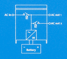
Energy goes into Ac-in and goes out of the two outputs. The little inverter block at the bottom can add to it (feed energy in) or it can take out extra energy (charge the battery), or it can switch off completely (eg when the battery is too low), but the bits at the top are simply wires with a big old switch in them. It doesn’t get hot or anything, it doesn’t do any additional work, the energy just flows through.
The only limit is to not do more than that big old relay is rated for, which is 32A for a 3kVA and 50A for a 5kVA. So your combined loads on the outputs must remain below this.
When there is a power failure, it opens the second relay (going to Ac-out-2) (edit: It opens both relays if you want to be pedantic) and those loads are dropped. So they might as well be connected to the grid.
So why do it that way? Well, because there is a current sensor on the input side, and when running ESS it tries to keep that sensor at zero (power). So by putting loads on AC-out-2, they will be offset by the Multi (the Multi will feed in power and push the input measurement to zero, if possible).
When you install a Carlo Gavazzi meter, then that meter becomes the point that is zeroed. This allows the Multi to also compensate for loads that are NOT on one of the outputs. This is often way more convenient than rewiring everything.
I used to expression “compensated” because strictly that is what is happening when the grid is on. The grid powers your loads. The Multi compensates and lowers your grid consumption. You cannot overload the Multi in this scenario, because it’s like a guy sitting on the side of a river adding buckets of water to it to make the watermill downstream spin a bit faster…
When the grid fails, NOW the Multi powers everything (edit: Everything on Ac-out-1) directly. And now you better not go over its rating, or it will shut down.
3 Likes
Marvelous! Thank you Izak!
Thanks all for sharing your knowledge!
And NOW I remember!!!
What I took away the 1st time I went 3kva, I’ve seen our house draw more than 10kw at times … in the scenario I painted above. Ps. I did not clean the garage either.
Because a normal house breaker is rated at max 63amps, with a 3kva’s max breaker of 32amps, I would have effectively halved the potential of the house overall when running everything through the MPII 3kva.
Versus installing a Carlo with the same 3kva, the 63amp breaker then stays in place, the 32a becomes a non-issue to consider.
If I can add I have used mylar cable to extend it.
Good choice, I always have a roll in my vehicle.
Ok so I use this Mylar cable to extend the RS485 cable. Where do I obtain this? Computer shops?
Another question please. It was mentioned that with this long extension, the ends should be terminated with 120 Ohm terminators.
What do these resistors look like, how are they fitted to the cable, and what about the USB side of the cable?
Last question, I assume the USB side of the cable goes to the GX device, in its USB port. Or can one of the VE Bus or VE Can ports also be used? Wondering this because of this 120 Ohm terminator thing - if I have to cut of the USB plug for this.
Jammer vir al die stupid vrae julle, maar ek werk nie elke dag met die stuff nie.
This morning I again considered the ZigBee modules and started reading up on them, until I saw that the one at the main db side needs a 12V power supply…
I mean really???
What would be the use of having something to transmit data wirelessly (obviously in cases where the inverter and more obviously the batteries is not in close proximity to the main db and giving it a 12V power supply?
Why can’t it be made to work on 230V?
The module on the GX gets its power from the GX so that’s fine.
Or am I completely missing something?