So I thought of a few things I would have done differently if I had to do it all again, I will do a list and add to it as I think of things.
I should have painted garage wall first or mounted everything on a nice board of melamine, the board option would work very nice if you have everything planned out from beginning.
I should have left space initially for the second inverter next to the first, didn’t think I was going to get it so didn’t plan properly.
Mount busbars vertically not horizontally just below inverters in point 2
Only get the 250/100 MPPT and put 6 strings of 4 or 5 panels north/east/west. But it is better off grid to have a backup MPPT so not complaining to much.
This is a maybe because I currently have almost zero volt drop between battery and inverter and don’t get any of the legendary ripple. But I could have gone 35mm2 for batteries just because its so much easier to bend in the trunking than 70mm2. But now that its in I can use those cables to double up batteries if i ever need too. Point 3 above would have also helped the 70mm2.
Gone with the renusol panel clamps from beginning as Jaco Suggested because they just so easy.
So finally got the time to parallel my two inverters and change DB board. Right now its running on eskom as I was short a piece of cable so hopefully tonight I can connect it all up.
I put a change over switch in my terminal panel so I can run either straight from inverters or straight from eskom, no mixing anymore. Once I’m happy will then apply for disconnection.
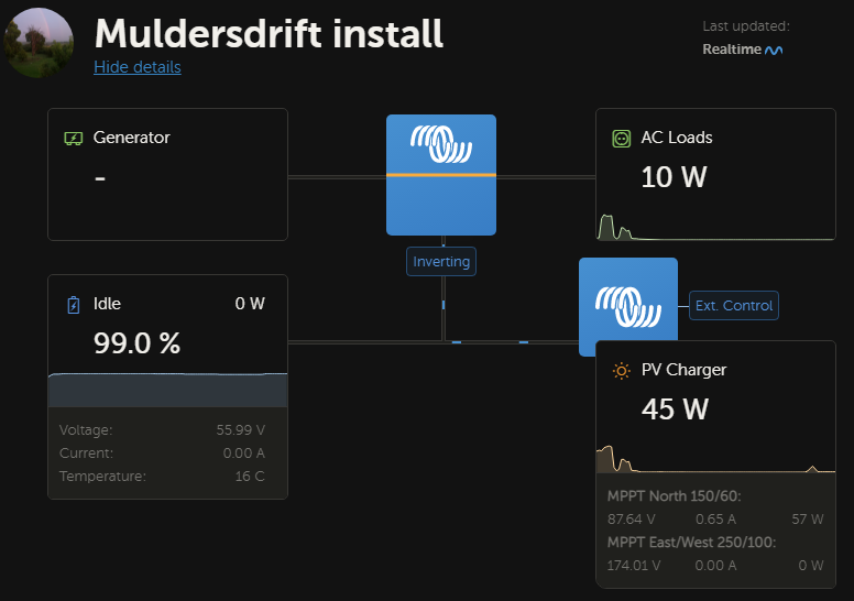
I have set up system to have generator backup so changed settings to suit, but have one question regarding the input current limit. I set it to 10A for each inverter, do I also need to change the charger amps or does that not matter as the input current is now set?
edit: just realized the 70amp is at 56V so well below my 20A 230V input so all good anyway.
settings file link removed
So this came up after I finished connecting and I’m not sure if it’s normal.
After switching on, the master inverter has the “inverter on” light solidly green, but the slave inverter is blinking both “mains on” and “inverter on” one after the other. The manual states this is the power control and power assist error light.
Is it supposed to only flash on the one inverter and why is it flashing, I thought power assist was only when the genie is connected.
It’s is still supplying power as normal and has no feed from eskom or generator connected.
@Phil.g00
I have a question regarding the earth cable from the municipality.
My eskom box is about 100-150m away from my house and there is a nice cable with separate earth running in the veld till my house. When I eventually get disconnected from the grid should I keep or remove this earth from my main bar?
Currently my earthing is all to one earth bar in my terminal box and a cable from bar to the earth spike outside. Then cable down from roof to earth spike and cable from fence also to earth spike. Eskom cable goes straight to the earth bar.
I think it should be ok staying connected to the municipal earth but would like more opinions.
OK, let’s think about this.
What you want to achieve is basically everything within your property boundary to have an equipotential earth. To achieve this you should connect everything (metal) from your fence inwards together to a very low resistance central earth via some sort of wire bonding.
I say “some sort of wire” because copper is expensive and I have been using recovered fence wire in my water pipe and cable trenches for a while now. And I have only seen benefits.
That said, the thing you don’t want to do is import issues. That means once you have created a decent earth mat, that you attract earth currents from far afield.
Now this where you are in the best place to judge your own answer. The plus may be that this municipal earth by virtue of being a long length of buried copper represents a very low resistance earth. The minus may be that now municipality system fault current or remote lightning still heads your way.
I think I’d consider a compromise, break from the municipality but maintain the earth cabling and incorporate into your own earth mat.
This is also what I was thinking but because its a nice long cable underground it should dissipate any faults I think. Maybe I should disconnect the municipal earth from my DB earth bar and run it straight to the spike instead giving it more chance to dissipate any faults but still giving me a nice earth connection.
Everything that is “dead” metal should be joined to everything else that is “dead” metal and the mass of earth within your property. This should alleviate severe voltage gradient during the passage of high earth currents.
The greater the surface contact that this dead metal has with the mass of earth the lower the earth resistance, which is also desirable.
My understanding of your situation is that you have a bare earth conductor from the municipality connected to your earth spike at present. And that in the future you wish to break ties with the municipality.
What you never want is two separate unjoined earths on a single property, so that municipal earth must always remain connected to your earth spike. On the other hand, you don’t want to import earth current from the municipality’s far bigger system.
I would consider something like cutting that municipality earth cable and bonding it to your fence, keeping it tied to your earth spike at the other end.
Coincidentally, I attended a presentation on earth potential rise in substations yesterday.
The typical Irish standard (220kV sub) is copper buried 600mm down of 95mm2 laid out in a 10 m grid.
The ground is then covered with substation stone, forming a high resistance barrier to human feet.
This still has to be supported by soil resistivity tests ( Ireland is a damper country than ZA). It is then tested via computer modelling that can identify unacceptable step potentials against future power system expansions.
Extra copper is sometimes needed as identified by these models.
It is easy to put in as the substation is built and difficult to add to an existing substation.
Interestingly, the model often identifies that extra copper is needed at fence boundaries and the corners of the substation.
A question, in a off grid setup like yours where you usually also have a generator for backup.
Can the GX be configured to only charge the battery when coming on or does it charge the battery plus supply the loads?
I guess this will also depend on the size of generator, whether it can actually provide a meaningful charge while also directly supplying the loads.
Firstly this is victron not axpert haha so it just works. jokes aside, you set the victron to limit the incoming current so it never overloads the generator.
You usually run generator because your battery is going flat and there is no sun. It will take power and run loads and use rest to charge batteries.
Edit: a 5kW generator will supply quite a bit of power to charge batteries. 70A at 56V is 3920W
It charges the battery and supplies the load. It charges the battery as fast as it can (max capacity), or at the maximum configured charge current (if you configured a limit).
There is also an AC input limit you can set. If you set that, it will decrease battery charging when a large load is started in order to make sure you never exceed the input limit. You can use this to load a generator to 80% of its capacity (the most efficient way), and then it charges the battery with whatever remains after powering the loads.
Generator power is expensive, so you want to charge the batteries as fast and as efficiently as possible.
Something else with generators which I didn’t see anywhere in the GX settings.
Usually you would start a generator and let it run for half a minute or so before putting any load on it and the reverse when switching it off again, first remove the load and only then switch it off.
Does Victron make provision for this in any way?
Victrons grid code takes care of this. It will only connect after the supply has been stable for 1 minute. When the Grid supply is restored, It will switch the loads back to the grid after all self checks has been done and 60 seconds has passed. Only after all this was done, it will switch the generator off.
There is also Dynamic current limiting. This transfers all loads to the generator slowly (or slower) to prevent sudden RPM changes due to moving faster than the governor on the engine
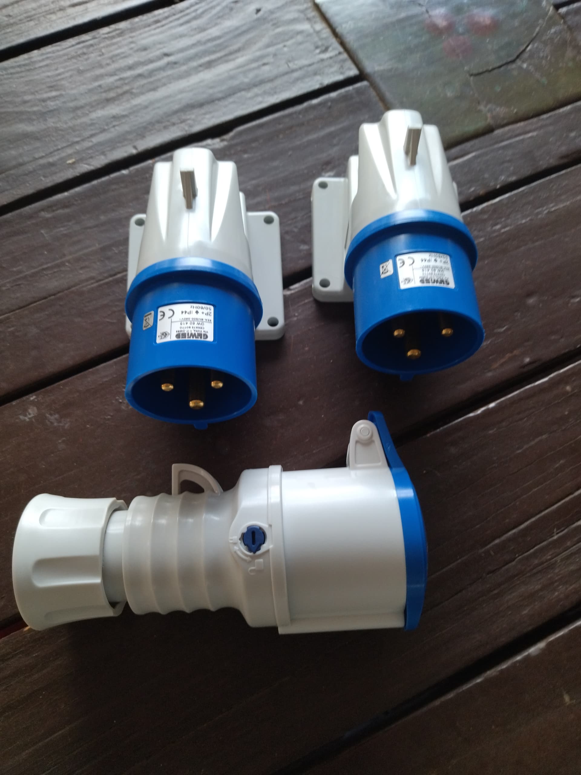
While we on subject of generators, I got some plugs for my generator set up. I’m going to have one plug going to the changeover switch incase I want to work on inverters and still power house, second plug is going to go to inverter so I can charge batteries and run loads.
For those who are interested:
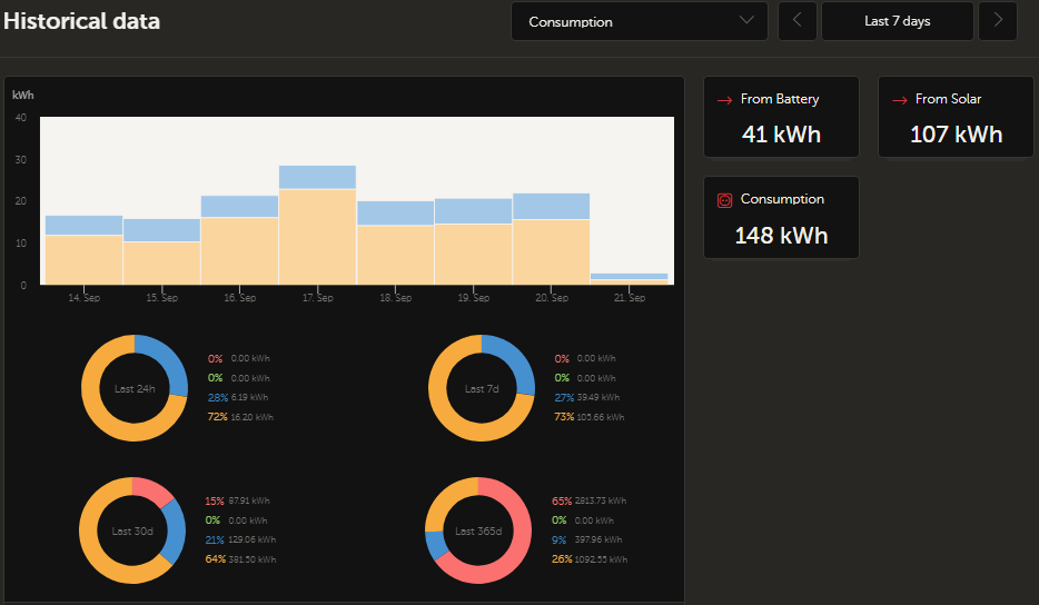
Its been a week since the off gird test and the weather has been good so not ideal for testing the worst conditions but I also don’t have my 12 x 445w panels up yet so the test has been with just the 16 x 435W connected. There was two cloudy days were I could not top up batteries so ran the battery to about 49%. Generally I use a third to 25% of batteries from sunset till sunrise.
I use the same plugs on my setup. My whole installation is in a 48u network cabinet, and it attaches to the house with two of these plugs. The whole thing can be unplugged and moved easily. Although, it is best to take out the batteries to reduce the weight, and then pull off the doors and side-panels, and you’d still need 2 strong people to carry it, it weighs as much as a piano… if not more.
The important thing to remember is these plugs are limited to 32A. Remember to put corresponding overcurrent protection in place.