There is a Pylon US3000, one cell in the middle pouch is dragging the whole battery. It stays @ 2.6v. How can i bring this cell to same SoC as the others? I am not sure if the BMS is doing a good job. With the inverter set to 1A, it’ll show that it’s charging to 100% then falls back to 0
If it’s that unbalanced, the only way I can think of is to open the battery and charge that one cell up with a DC power supply. I would probably start at quite a low current and keep an eye on it for a while to make sure it’s not getting hot or anything.
The BMS in a Pylontech battery uses a passive balancer that bypasses around 50mA across high cells. That means a badly unbalanced battery will end up pulling a low cell up at 50mA charge current. It will take an inordinate amount of time to recharge a 50Ah cell at 50mA (a thousand hours, or around 1.5 months).
If under warranty, I would pursue that road first. If not, I would do what Stanley suggests: Individually bring the low cell up. That means opening the module.
2 Likes
already opened, so no warranty
i’ll try to isolate the cell however, do I have to desolder from the pack/pouch? see how they are PYLONTECH eBay solar storage battery teardown faulty repair BMS battery swelling 54v pack - YouTube
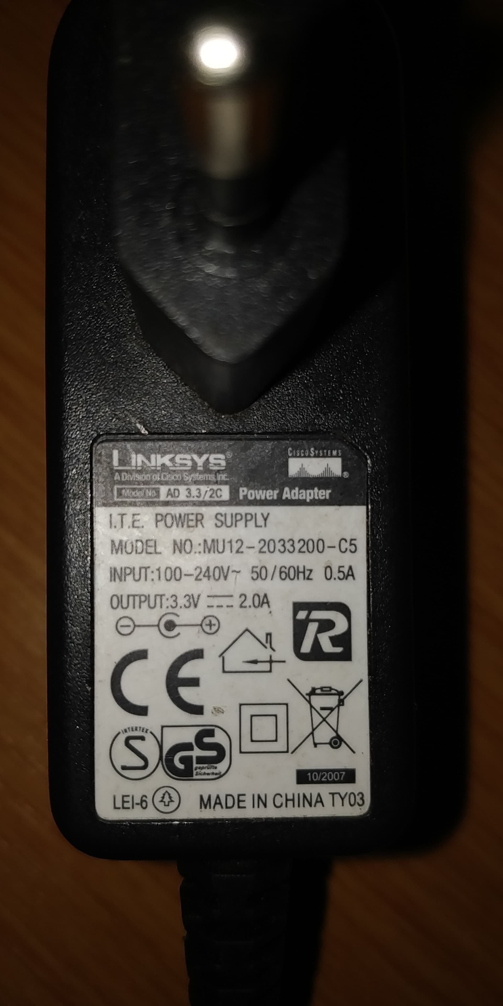
Any DC power supply, a 19v laptop charger or 52v PoE switch adapter?
thank you
The cells are 3.2V each. You need to have a charger capable of charging 3.2V LiFePO4 cells and not overcharge then or they will burst into flames. ![]()
If you can get the cell to 3.35V-3.40V the internal balancer should be able to pick it up from there (assuming the rest of you cells are also then at that range)
Lithium cells can easily cause a fire. Don’t just put any power supply on them and leave them alone.
1 Like
If the cell terminals are accessible then you don’t need to disconnect it from the rest of the pack. You will need a variable power supply though. One that you can adjust down to about 3.4V at least and set a current limit.
As the others have said. If the terminals are accessible, then you need a power supply (current limited preferably) that pushes 3.3V to 3.4V with small crocodile clamps so you can put it directly on the terminals. And then just wait for the voltage to pick up.
A bench supply is probably what you want.
1 Like
According to this video, the terminals are not accessible. You will have to disassemble the packs and reassemble afterwards.
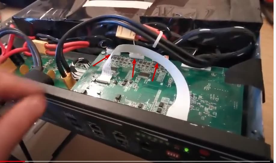
Replying to myself here. If you know what you are doing, you can also unplug the balance wires, and use that to gain access to the individual cells.
1 Like
Just a heads-up.
Once I used those teeny little wires, a little thicker than the balancing wires though, having gotten the charge amps a teeny bit too high, and promptly the wire started melting.
Just make sure of the max amps those balancing wires can handle to re-charge that one cell.
2 Likes
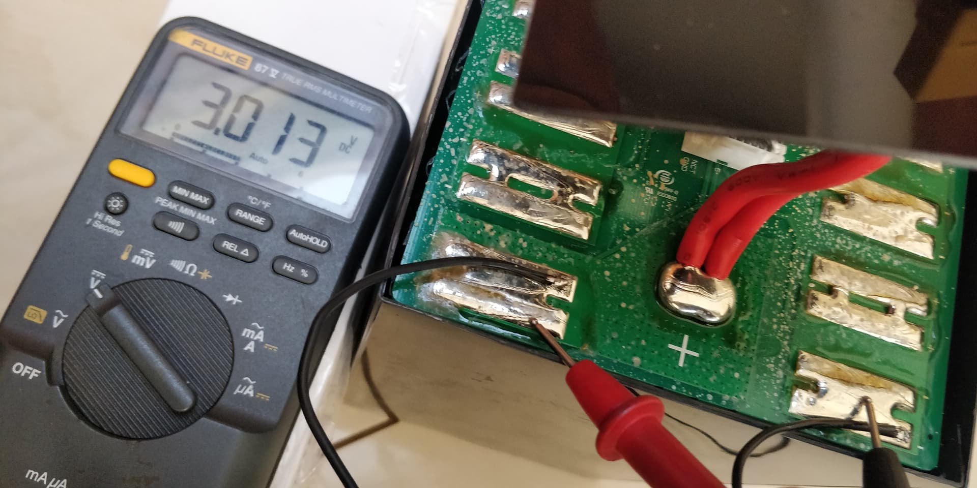
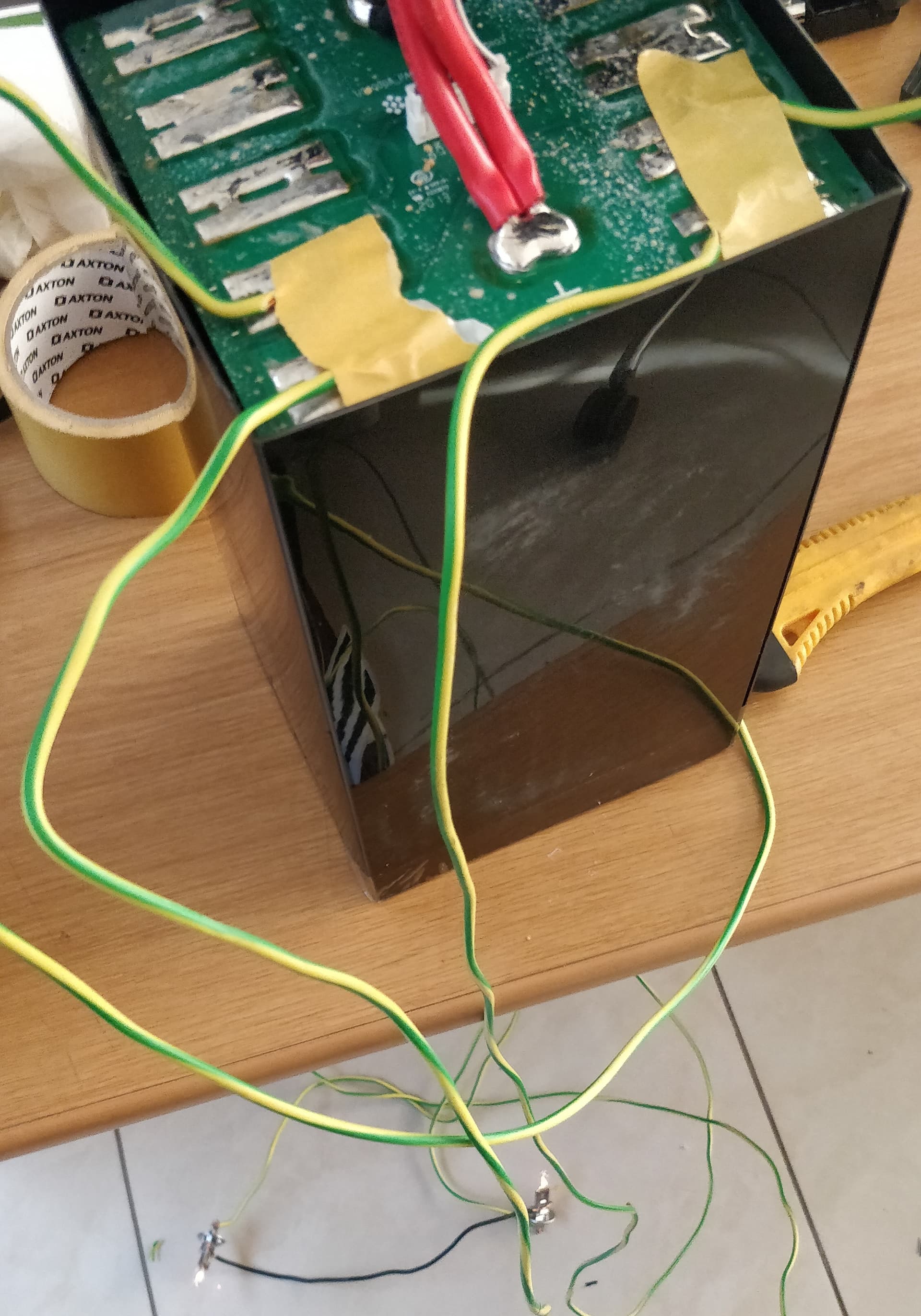
The white wire is the main -ve of the pack while the others are the +ves from cell 1 to 5. using a volt meter with the -ve terminal stationed at the white wire, you’ll read increasing voltage from cell 1 to 5 (they’re in series).
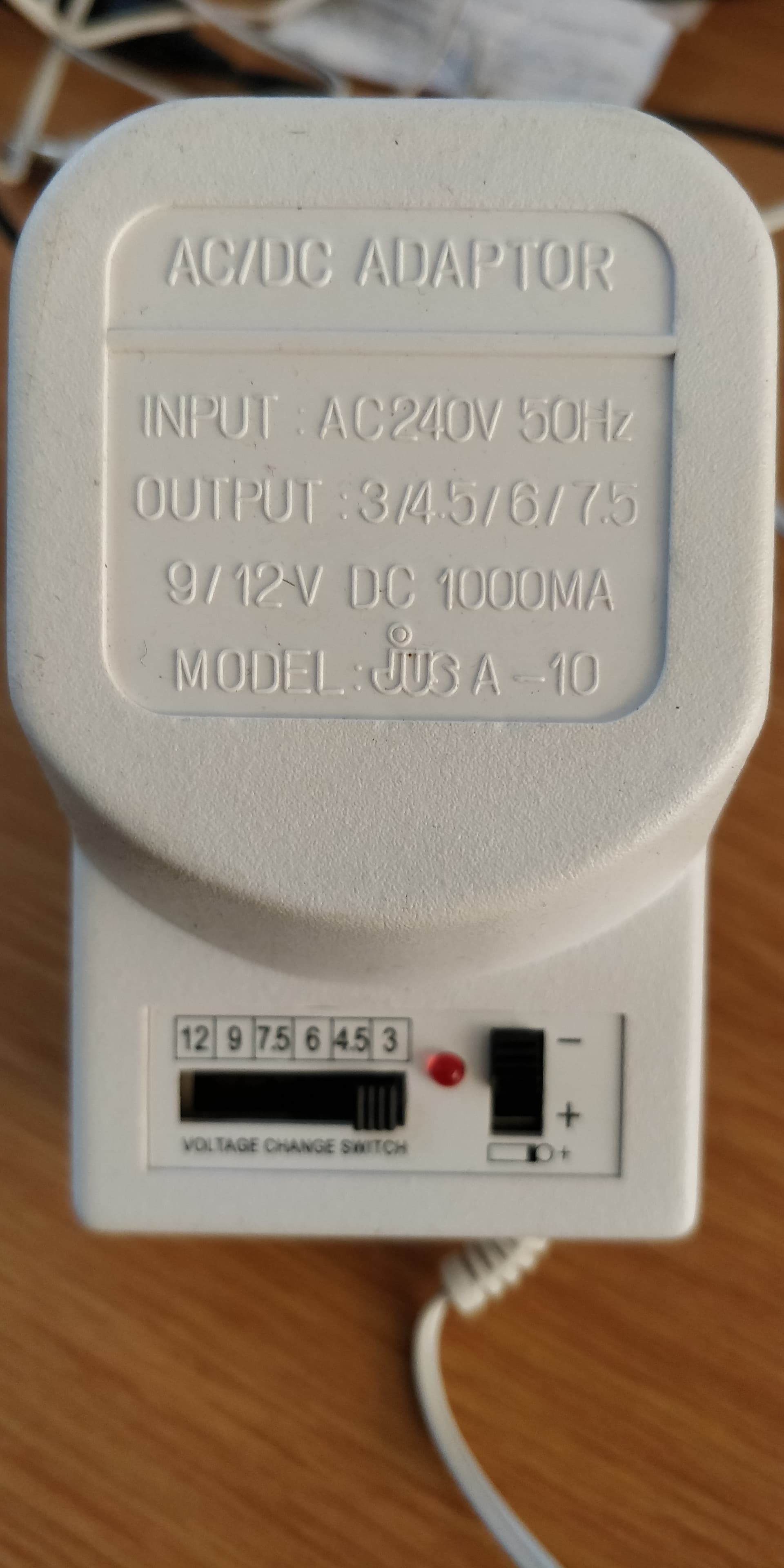
In the video, i saw that he could measure individual cell volts. I’ll find the weak cell’s terminals in the same way, solder a piece of wire each and then clamp this dc adapter to the wires.
Question is, how long will it take this 3.3v @ 2A adapter to charge the cell from 2.6 to 3.5?
50Ah ÷ 2A = 25hours? I’ll constantly check and see.
This is fun ![]()
I think 2A is too much for that thin wire. But if we assume it is a 50Ah cell, and it is completely empty, then it will take around 25 hours to be completely charged.
I’d still feel safer if it was current limited.
Now if you had a discharge tester (cheap ones are like R300) you could check the capacity of the cell too.
There must be a reason it ended up in that state. I mean… other than self-discharge perhaps?
OOooo nice!! A fluke 87V. Nice multimeter. I got the 88V one.
And the end result @SolarIsDeWay? Success?
1 Like
I am about to put the cell packs back into the case for the third time and see what happens. I have managed to get that one cell up to 3.21v…also had to discharge others as well…manual top balancing, I guess.
DISCLAIMER! DON’T TRY THIS UNLESS YOU KNOW WHAT YOU’RE DOING.
I don’t have the right tools, so i make use if what I can find:
discharging 16v pack with 18v speaker:

discharging individual cells with car 12v bulb:
1 Like
It’s not top balancing unless you take it to 100%. The problem is the flat voltage/SoC curve. Unless you take them all to a known SoC, you will soon find them out of balance again. Since the BMS only does balancing at the high end, the only way to know they are balanced is to top balance them. That means taking them all to ~3.6V (could be as low as 3.45V, but you would have to keep them there for a long time until they stop taking charge).
My suggestion is to get a 25A 3.6V charger, either borrowed or bought, and balance all the cells separately.
Perhaps one of these:
Neither will do 25A, but both can do 2 cells at a time - 2x12A and 2x15A respectively.
1 Like
Thanks @_a_a_a
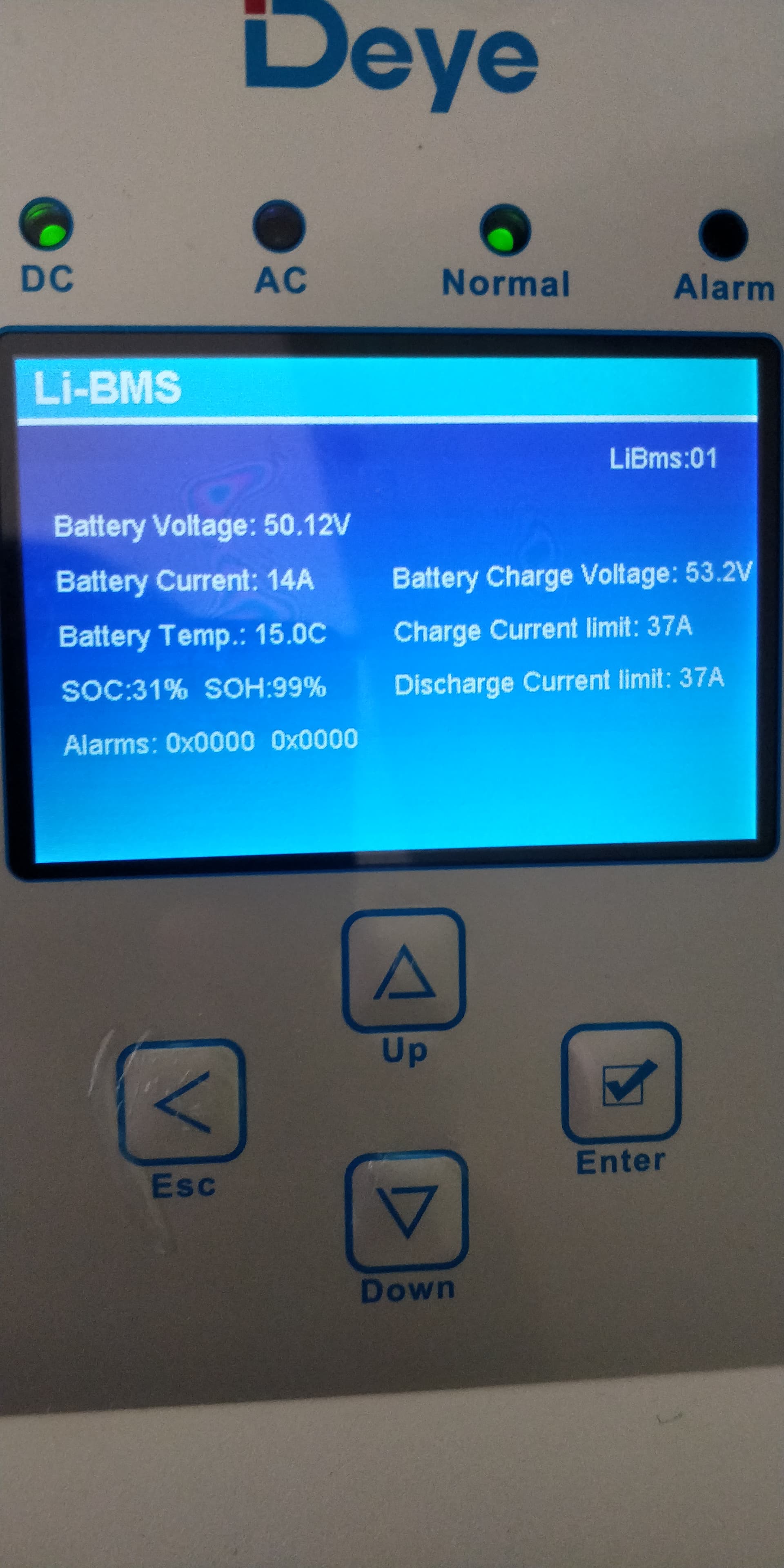
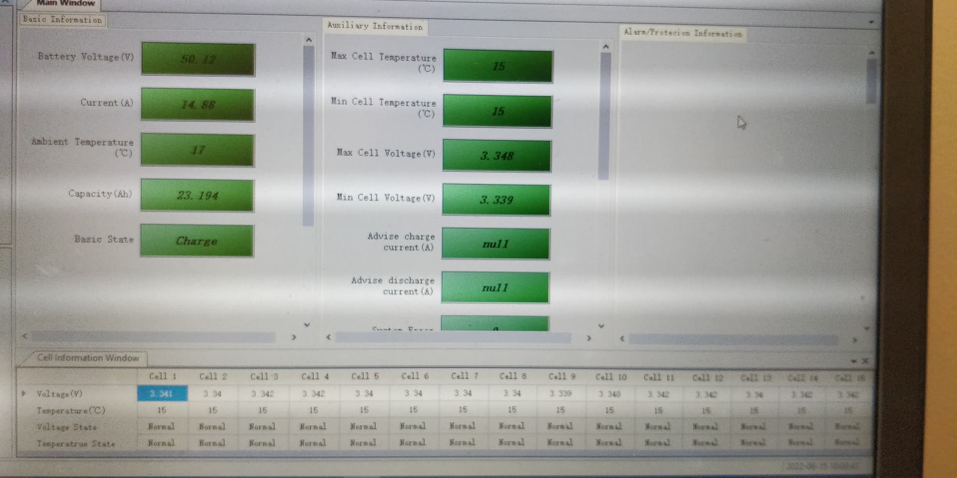
I managed to bring the cells up to 3.6v and observed these:
The one cell that was initially at 2.6V seemed to struggle to hold charge @ 3.6V. So I charged it last and quickly put the everything together and the BMS took over.
The battery’s max charge limit is 37A but @ 20A I saw some cells charging faster that others. I further dropped the inverter’s charge limit to 10A and noticed some consistency across the cells.
Today is day 2 of use and I am currently charging from @ 15A limit.
So, I hope it’s working