Fronius MPP Voltage Range

So far my reading up haven’t really touched AC coupled PV inverters like the Fronius Primo 3.6-1 and I also haven’t really seen a lot of posts / installs with it. It is starting to look attractive to me, so I am trying to wrap my head around it and thought I’d start by asking for some assistance here as Fronius now has me confused.

My idea is to have a 5kVA Multi along with the AC coupled 3.6kW Primo.

Looking at the technical data for the Primo it shows that the MPP voltage range is 200 - 800 V which is obviously where you would like to be to get the most out of your PV panels.

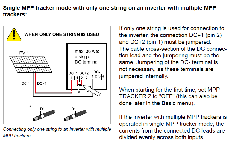
The inverter has 2x MPP trackers. I first assumed that the 200 - 800 V meant the total voltage across the 2x MPPT’s and not per MPPT. I’ve since started thinking that it means per MPPT because in their ‘recommended’ configuration it seems to be 1 string and ‘jumpering’ the 2x MPPT’s which seems to be the easiest way of getting to the 200V earlier. Does anyone know for sure?

In my specific case I will have East and West facing PV, so I would ideally want to have 1 string on the Eastern roof going to the one MPPT and another string on the Western roof going to the other MPPT.

Fronius has a nice Solar.Configurator tool which is quite handy. It has the JA Solar 345W (JAM60S10-345.MR) panels which I’m not specifically looking at, but the Volt & Amp differences are negligible between models. It shows that you can wire them all up on 1 string (the installation manual shows that you connect them all to MPPT 1 and then add a jumper to MPPT 2 and switch off MPPT 2 in the configuration), or you can (with 10 panels) do a 7/3 split between the 2x MPPTs. The options are 1x10, 1x7+1x3, 1x6+1x4, 2x5 (one MPPT), and 1x5+1x5. That seems to be an order of preference as well.

My guess would be that the 3 panels in a 7/3 split won’t reach the maximum power point as they’ll do ~105 V at 25C, but the 7 panels will be operating at MPP as they’ll do ~245 V at 25C and ~200 V at 85C. But the smaller string will at least start feeding as the inverter starts at 80 V.

How big will the difference be when operating at MPP versus not? I’m just trying to figure out how big of a difference it will make and if it won’t be better to just move it all to 1 side and have it all on 1 string running at their MPP.

Although while typing this I realized that I’m just overcomplicating it. I also though about adding a couple of panels on a DC coupled MPPT to help charging more efficiently and also add to the loads, but I though about first seeing how it does using just the AC from the Primo as there should be enough capacity once the geyser is done to still charge up the batteries even if it is less efficient.

I might as well just add a couple of panels and a DC coupled MPPT from the start to the East which can help out with early morning loads and some charging and then have 10 panels on the West on the Primo and schedule the loads to only start when the Primo starts generating after which the DC MPPT can charge the batteries along with what’s left over from the Primo via the Multi.

That would be an incorrect assumption. That would be per MPPT.

An MPPT is a buck converter. Well in the Fronius it is likely a buck/boost converter since it can take a PV input of lower or higher than the peak grid voltage (325 - 350V), so more generally it is a DC/DC converter.

This inverter has two of them, but from your post it sounds like you can disable one and simply connect both strings to a single tracker. Not quite sure how that works exactly, but it sounds like they added a convenience function so you can use those terminals for a second string, while having them connected to a single tracker.

I would expect the best voltage to be a little higher than the peak grid voltage, so you should aim for 380V-450V ish per string. But that would put you over 10 panels per string. My gut feeling is that you want to go 1x5 each on its own tracker (one for east, one for west). but then the voltage ends up on the lower side (5 x 72-cell panel. your Vmp will be around 180-200V). Not ideal. If you had 12 modules, you could go 6 on each side.

With an east/west setup, I would expect 1x5+1x5 to be better than 2x5 on a single MPPT.

Splitting them 6/4 may also work (if the voltage is high enough), if you know that your mornings or afternoons are busier. Then put the modules on the side of the house when most energy is being used.

Also, I have a Primo (a 5kVA) on the test bench. It starts up around 80V. I can only assume that is why the configurator recommends as low as 3-series, cause that would be way below the 200V quoted.

Yeah, I figured that out as I was typing the post and ended up correcting things 60 times.

There are 2x DC+ terminals per tracker, so I’m guessing you can just add both there, but then you aren’t able to jump the 2nd MPPT. The only thing the manual shows is that you can combine the strings and then run a single cable to 1 MPPT and jump the 2nd one, but that’s not the same. Unless it’s a case of using the 2nd terminal. Here’s a screenshot from the manual showing it for only 1 string (it’s the same for 2 strings, except it shows a combiner after the 2 arrays):

That’s good to know, thanks. I’ve realised now that with the Fronius I need to look at what I now call the “Vmp per Wp” and not just the “Rand per Wp” in order to get as much Watts as possible on a string. I’m guessing it’s better to use the Vmp at NOCT than STC?

That’s where the ET112 will come in handy along with trying to shift some load around once we’ve moved in. From what I can tell the gigantic oak trees on the street will be blocking sunrise in any case, so it may be best to just look at putting them all in one string on the Western roof and try to move some load around.

Correct, the tech data also shows it starts up at 80V, but as it’s better to have a higher voltage I’ll rather try and get it to within the MPP range (and above grid voltage) to actually benefit from it.

I guess the main thing would be to get the ET112 up and see where the loads are and try and move it to the afternoon and get one string or go with 2x strings with more panels per string to at least reach ~240V per string.

I cannot imagine that there’s much difference? As far as I understand, the current is proportional to the irradiation, but the voltage is pretty much around 0.6V-0.7V open circuit, and pulls down to around 0.5V per cell under load. So a 72-cell module has an open circuit voltage somewhere around 45V and pulls down to somewhere between 36V and 40V at full power. Which means at 3 panels wide, that’s somewhere between 115V and 150V. Ish. With lots of handwaving and thumbsucking.

Then, at STC you will get 9A out of them and at the more common lower levels we have around here, probably about 8A-8.5A. Ish.

Yeah, not really. I think it was more my overcomplicating of things as I was thinking of trying to size the array based on potential irradiation levels to have just enough for 380V - 450V.

I just looked at the house again and realised that the West roof is slightly angling South, something like 252 degrees or so, so it might not really be worth filling that roof up.

It seems like there might be enough space for 9 panels on the Eastern roof (I’ll have to measure and check shading after moving in as I think 2 or 3 panels might get shade in the mornings), so it might still be worth getting the Fronius, otherwise I’ll just go for DC coupling and get in line with Saffer way.