OK, that’s that then. I was hoping to easily comply with CoCT’s ridiculous 15A grid-charge rules for batteries using that setting, but it’s detrimental to AC-PV charging too. I really don’t get how they can think up that rule.
But with ESS it isn’t really an issue unless “Keep Batteries Charged” is on, which will just require changing that setting at the same time. Although it still wouldn’t comply, since you could just not do that.
Not dumb, but also not a problem, unless you keep your batteries full all the time.
When there is PV, the grid-tied PV inverter pushes it back. If the MultiPlus can see it, either on its AC-out or with the help of the ET grid meter, it “pulls the power down” into the battery and charges. Any excess goes onto the grid. This works for any brand of AC PV.
The Modbus control of the Fronius from the Cerbo (and one or two others) allows it to not go onto the grid as well, i.e. limiting export. This also works with the Fronius’s optional Smart Meter without the Cerbo, and I assume with any other brand that has a grid meter to limit power. The Victron kit then isn’t in the loop and the PV grid meter sees the battery charging as a normal house loud. You would then have your ET & AC PV grid meters back to back, possibly tweaking the grid import threshold a bit. (Mine is currently like that, but not for that reason.)
In either of the ESS “Optimized” modes this just works, since you tell ESS there’s AC PV somewhere, either the input or output. If you use “Keep Batteries Charged”, then there’s nowhere for the power to go, so you lose out. But the same would be true if you charged with DC MPPTs.
So what you are saying is that there is still a need for a maximum charge power setting.
There is a slight difference in where things are implemented with these two settings. The newer one that DVCC uses (the current limit) is implemented in the Multi. The GX device merely relays the information from the battery (or from you) to the Multi. The limit applies regardless of where the energy comes from, because the point of this feature is protecting the battery.
The older power limit setting, affects how the ESS control loop sets the “setpoint” on the Multi, in other words the work is done on the GX device. The setpoint is continually calculated so that after the loads is covered, not too much extra is imported for battery charging.
Because the calculated setpoint acts on the INPUT of the Multi, which is inactive during an outage, that setting does not affect PV-inverters on the output, as the documentation says. It is not really a feature, it is documented more as a quirk one might say.
Of course there is a lot of overlap between the two types, and as it always goes with these things, it causes confusion. So one went away…
Yes please. If I could name it, it would be “Grid import charge current limit” – i.e. only take this much current (or power) from the grid to charge the batteries (but only when you need to!). It is about the position of the ET, not AC-in or AC-out, so it can only be implemented from the Cerbo, presumably tied to ESS.
It is not:
a grid limit,
an AC-in limit or even
a charger limit,
it is specifically “grid current going to the battery”.
Meaning that the following should be excluded from the calc:
AC PV on AC-out gets a free pass through the charger
AC PV on AC-in gets a free pass through the charger
any loads on AC-in or AC-out gets a free pass
Current should still be clamped to the Multi’s charge limit or the DVCC charge limit of course.
(Hopefully if I make it sound complex enough it’s fun to build!)
In terms of the DVCC feature goal, your explanation makes more sense than the manual. If you want that feature, it should work all the time, like it does now.
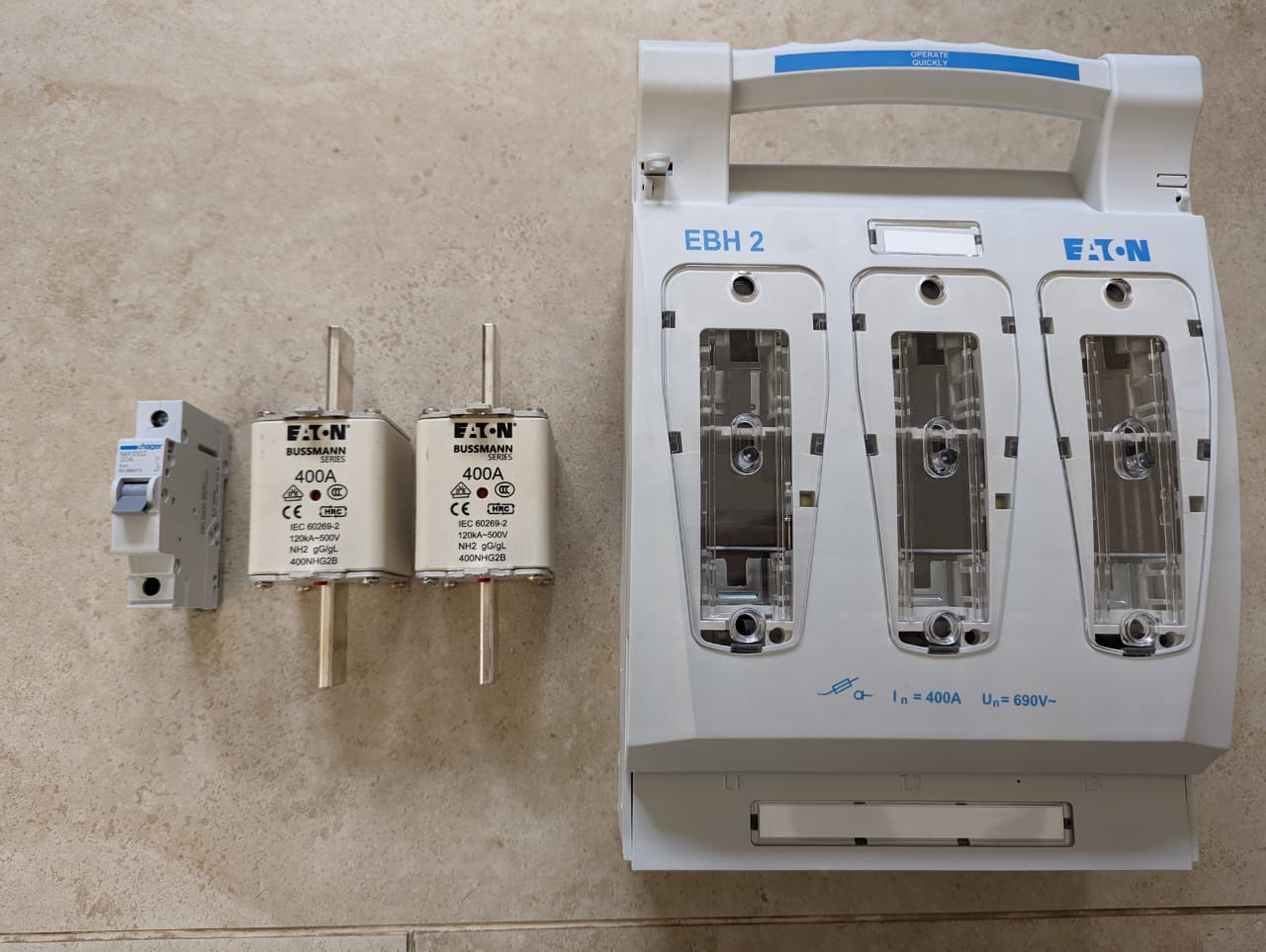
I think the problem with the breaker is not that you cannot have a breaker, but it needs to protect that battery cable. With a 400A breaker the battery cable would have be as think as my leg
Yes and no. Electrician specifically said the 2x 50mm2 cables are fine (that’s also how the battery ships).
However, the fuses need to be 2x 400A, one per pole. You cannot put a 200A fuse per cable, you must join the 2x cables at the fuse entry and again at the exit.
So “protecting the cable” is correct, but “the cable” in this case is both 50mm2 conductors together operating as a unit. When the fuse blows, it needs to disconnect the entire pole, not just one conductor. And the same for the other pole.
You may create larger conductors by combining smaller ones, but then there may be no other equipment in between: the combined conductor may not be split and all its pieces must follow the same path.
I specifically asked since 200A fuses are a lot easier to come by (and go in cheaper enclosures), but he was very clear on that. If you have multiple batteries each can have their own fuse to a busbar and loads can have their own fuses from the busbar, but this isn’t that.
The breaker itself is actually fine: it’s properly DC rated for 400A from 12V to 500V, breaks both + & -, and can do so under load, breaking capacity 25kA. But it’s not 2x fuses, and as he reads the regulations, it should be fuses.
As far as I know, you can put a fuse only in the positive line and then use a breaker as a means to disconnect both lines. This fuse should go as close as possible to the battery so that a ground fault in the unfused part (before the fuse) is unlikely.
Due to cost, most people just fit a Mersen/Jean-Muller fused disconnect to do both jobs. You are allowed to put a link in the negative side.
If you decide to fuse both lines, when using a BMV or smartshunt, the fuse comes AFTER the shunt. The shunt has a 100mA fuse for its own supply.
I’m actually not 100% sure what happened to be honest.
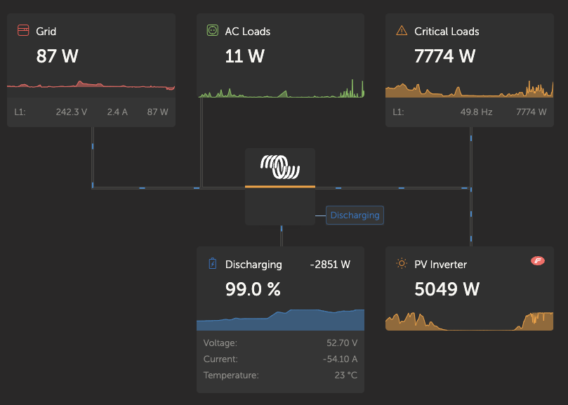
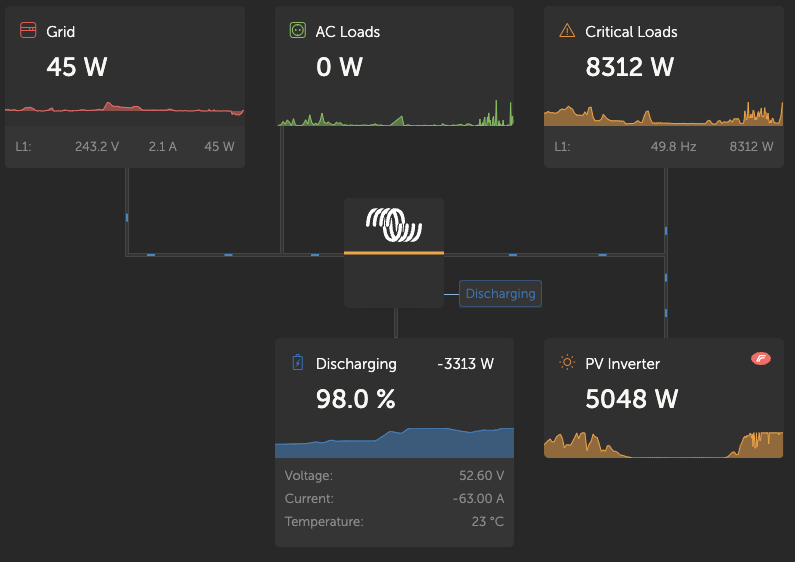
Grandma wanted to make us stuff “for the freezer”, so there was stuff in the oven, like 2kg pumpkin cooking in the microwave, lunch was made for kids coming home from school (toaster?), kettle going and probably washing machine and dishwasher. You would almost have to press every start button at the same time though.
The inverter cupboard hasn’t been installed yet, so I just heard the fans going crazy through the headphones
Good example of the Fronius and Victron working together, although that wouldn’t be very stable if the grid wasn’t there.
Well in my case, the pair is quit reliable. On switching off large loads, sometimes Fronius goes off line but recovers within a minute mostly. The dual Quattro’s carry on as per normal even so. All of this with Utility switched off 24/7
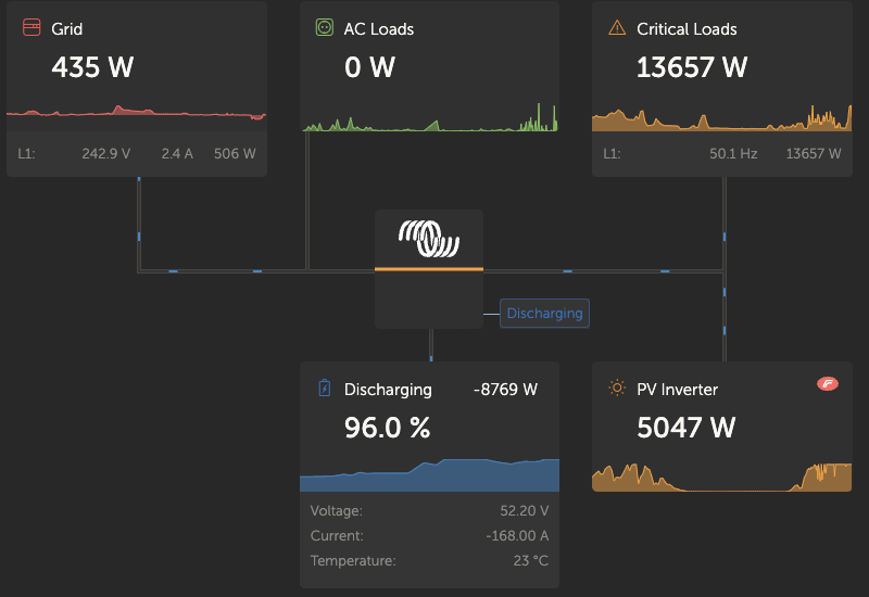
Yeah, that’s what I mean, the Victron system has to carry the full load every once in a while.
I’ve also seen that the Fronius (my Fronius?) doesn’t respond that well or that quickly to frequency changes from the Victron. In my case it doesn’t ramp down its output fast enough at 51Hz or so, causing the Victron to up the frequency to 52/3Hz, shutting down the Fronius entirely. It then takes a while to start up again after the battery SOC drops and the full 5kW can go somewhere.
This cycles a bit, which is why I’m saying it’s unstable, although the loads stay powered.
I’ve been meaning to investigate the frequency settings a bit to see if I can tweak the Fronius curve to respond a bit faster to the Victron in this scenario, but it’s only an “issue” during load-shedding with a fullish battery at max production time, and then you don’t mess with it…