Nope its firmly screwed onto the board that I put under the inverter, i lowered the inverter to get cable to fit. Must post some more pics.
Honey… someone is wrong ON THE INTERNET! cracks fingers… this will only take a minute…
WHAT DO YOU MEAN Han fired first!?
Yes, a lot of the time “angry” and “sad” look the same from the outside…
Oh absolutely. I firmly believe that a lot of conflict is borne from fear or at least the perception that there is a threat.
The reaction of some people to the pandemic and all the things going on with that is a perfect example. I mean, I don’t want to really derail this into a debate about medicine… but it’s the most recent example for me. You are barely over the shock of how this thing derailed your life, when people start telling you there is a medicine that you MUST take. You don’t understand this thing, you are not equipped to understand this thing… heck you’re day job involves visual arts (or something suitably far removed), so this new information is perceived as a threat, which leads to distrust, fear, and then conflict.
I find it extremely useful to ask, when in a situation of conflict: What are you afraid of? What am I afraid of?
</soapbox>

So after some datasheet-diving, the 8 & 10 KVA Multiplus II models definitely DO NOT support parallel (or 3-phase) connection, despite what the general MP-II manual says, so the 5 + 5, probably at a later time, makes the most sense. Even more so when I realised that 5KVA = 4000W, i.e. 8000W for 2x, whereas the 8KVA is 6400W. (The 10KVA is also 8000W, but it costs quite a bit more than double the 5KVA which puts it out of my price range.)
As @rautenk said, I don’t think I can really go wrong with a MP-II 5000 right now, leaving space for #2 if needed.
Next question… I’ve been plugging my garage panels’ info into the Victron MPPT calculator, but I’m not sure I fully understand what I’m seeing.
For 4S x 3P I get the 250/60 recommended, but “Min. PV voltage @ max. temperature” still shows red. See here.
For 3S x 4P I get the 150/60 recommended, but “Min. PV voltage @ max. temperature” is still red. See here.
What should it be?
FWIW, I’m still not sure I’ll actually use the panels, or all the panels. Just want to make sure I’m understanding the tools correctly. I’m attaching the panel datasheet if anyone feels like checking the values.
I don’t see that…
Edit: Oh nevermind, it required an extra click…
It looks like a bug to me. It is supposed to light up in red if your string voltage at max temperature drops too low for the MPPT to work.
As an example, the MPPT needs 5V above battery voltage to start, and 1V above to remain active so if the Vmpp voltage drops below about 59V due to temperature, or the Voc drops below about 63V, you have a problem in most 48V systems.
OK, that makes sense, because if I push the voltage coefficient to something like -1.5%/C, I just get no compatible MPPTs, never a green number. The closest I can get is with -1.0861 %/C which ends at exactly 49V, matching the MPPT min. input. Anything more and just no results.
Thanks.
Making some progress after a call with the City…
The electrical COC needed for transfer needs to explicitly indicate that “a PV system is present, but has been disconnected and is not in use” in the comments.
I can then proactively apply (i.e. don’t wait for them to find me) after transfer pleading innocence and amnesty, which should sidestep the fine. Hold thumbs.
(Aside: the system wasn’t registered. If it had been, I could just apply for the modification without issues.)
So, Howzit from Muldersdrift Somerset West!
Finally decided to bite the bullet. Will be installing a MultiPlus II 48/10000 and FreedomWon Home Lite 20/16. The solar expansion will have to wait for now.
Doing any of this during Stage 6 Load Shedding was bound to be a nightmare, but @JacoDeJongh managed to somehow source the MP and accessories while everyone else was quoting lead times of 22 weeks on the inverter.
As part of this install I also need to split the main DB as well as the “kitchen” DB, which is actually 75% of the big consumers, on the other side of the house. Getting another feed for essentials through to there is proving to be prohibitively expensive (no connecting roofs), so will be following @Sarel.Wagner’s “all loads are essential” model, but with my own loadshedding added.
All of Jaco’s packages have been sitting here waiting while the battery is on its way from Durban on a shipping plan I’ll call “Economy Lite Minus”. Yes, FreedomWon is in Cape Town. Yes, I am in Cape Town. Such is the way of stock shortages. Apparently they’re actually in JHB.
An EM package is out for delivery, so I might be able to start over the weekend.
Will post progress here – if you see something, say something, please!
Cool looking forward to reading about it.
Just want to make sure you know that you cannot parallel the 10kW multi so will be stuck with that size. If you happy with that then perfect. ![]()
Yeah, pretty happy with not paralleling (but that’s why it’s the 10kVA and not the 8kVA model). It can do 3 phase (and 2/3 phase), so if really needed there’s options, but that is A LOT of power.
Too much power is just enough. ![]()
Interested to know what your thinking was behind choosing the FW battery over anything else, I also rate them quite highly.
Please keep us updated, it’s going to be a very lekker setup.
For one, I like “local”, or as local as a lithium battery can get.
Secondly, warrantees are only good if the company is around to honour it. FreedomWon has been around for years now, so I’m willing to roll the dice.
Thirdly, the fact that comms includes a “please charge me at xx.y V” message makes me very happy when coupled with a Victron. Of all the local people they seem the best integrated with Victron.
Lastly, the Lite range is fairly compact for the kWh.
My 2nd choice would have been Pylontech. Not hitting local, nor CVL, but warranty, company longevity and general value for money seem great. Would have needed a bunch of modules to come close to the Victron’s max discharge rate, but might have worked out okay.
Although its not supported they have been paralleled successfully on a few sites by a few different installers.
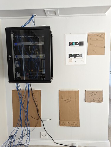
Installation is going to be on this wall:
Will build a “cupboard” over it in future with fans in the ceiling and vents at the bottom. The MPPT (right bottom, two options) and PV DB (right top) won’t come in now, but want to make some space available.
Almost impossible to prevent trunking from crossing. Completely impossible if you want straight lines everywhere. According to the manual the MPPT only requires ventilation space above and below. The MPII requires 10cm all around, but there are no vents on the sides at all, so I’ll steal 40mm depth on its left for the trunking. Battery isolator will go in the middle, and the Cerbo and bits (man, there’s a lot) will go in the cabinet.
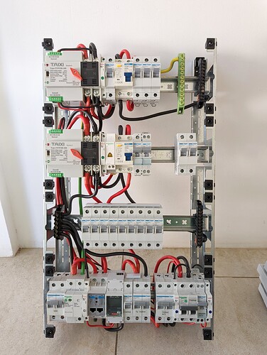
EM delivered short, so all the breakers aren’t here yet, but I started building the DB replacement – really a pleasure being able to work outside the box until the end! Used 16mm flexible panel wiring with crimped bootlaces as the house wire was just impossible for work with, except for the earth.
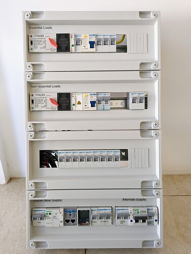
The grid supply / metering / alt supply section is quite a train. Briefly considered renaming myself to @hagermeister, but couldn’t get hold of Type A earth leakages and their surge protection options are ridiculously expensive. But you’re really punished if you’re using multiple brands, even different ranges in the same brand: nothing lines up outside or inside! ![]()
There’s a couple of placeholders in there to get spacing right, but the basic idea is this: Two ATSes to switch between inverter output (preferred) and grid. These can be manually overridden as well.
- The essential one is wired as you would expect
- The non-essential one will be used to implement my own load-shedding: it’s “grid sense” is wired to the essential output, so will always have power, even if the actual grid is down, and the “inverter sense” is wired to the inverter’s AC out 2. (The actual inputs are still grid & inverter AC 1.)
I’ll use the relay assistant to shed AC out 2 when load is too high, which will then trigger the non-essential ATS. Here I could use AC out 2 directly or contactors, but would need manual override in any case, plus I had the two ATSes left over from a previous project. These specific ones are a bit deeper than standard, so had to wangle the cover seats a bit to get it to close, but working 100% now.
So during grid failure all loads will be serviced from the inverter output, only shedding non-essentials when load is too high.
The sub DB in the kitchen will be fed from the space where the yellow LED is temporarily… i.e. before the earth leakage, as there is another in the kitchen. After EL is the geyser, pool, aircon and most of the plugs.
The Fronius Smart Meter next to the ET112 may seem odd; decided to install it since I had it, and the Fronius will be configured to fall back to its own meter if the Cerbo ever checks out. The alternative would be to shut down completely or feed back 100%, neither of which is great. And on the subject of the Fronius: it’s on the MP output, so if the MP is down, it will be down too – no changeover for maintenance as there’s simply no more space.
This is something I discovered rather recently, which is a little funny since I maintain code for that! You can tell the Fronius the priority of control, placing modbus first (which means it listens to the Cerbo), but it’s own limit second (so it falls back to its own meter).
You can also set it’s own power limit as the second priority without the Fronius meter, then it simply goes to zero when it hasn’t heard from the Cerbo in the last two minutes, which is also a good failsafe.
The limiting instruction sent by the Cerbo is always valid for 120 seconds. Good enough to be hardcoded.


