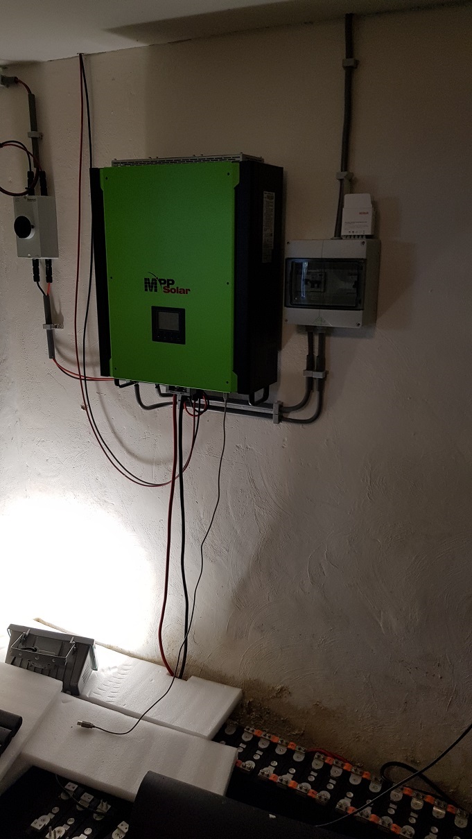
Furthermore the system exists of an MPP Solar hybrid inverter MPI 5K
On MPPT 1 are 18x340 Wp Trina panels in series and
on MPPT 2 are 12x260 Wp old panels that I took of a roof and reused
There were 18 of them but because of the specs couldn’t do more in series then 12. They are 60 V Uoc. So I purchased a PCM60X solar charger to connect the last 6 panels. Communication between battery and inverter will be done by a Raspberry Pi with ICC software.
Everything I need is here. I have 2x16 cells connected to the inverter now. They where top balanced before I put them on the inverter and I am the BMS and check voltages every now and then. They remain very stable. I had a Chargery BMS connected before but that thing was way of with the cell voltages. Its been send back to Chargery where they calibrated it again. I didn’t use or try it yet but the plan is to make another 10 kWh battery with it so the total will be 50 kWh.
There is an upload option in the edit box, or just drag the image in. If you don’t see it, then it might mean you don’t have that privilege yet. I thing there is a quick tour with the site’s bot that will allow you to upload pics?
Today I spent a while on the battery. I realy don’t have time lately due to work, SWAMPO complaining I didn’t finish the veranda yet and now I’m building an above ground pool for her. That must be heated by the solarsytem of course. A 17,5 kW heatpump is waiting to be connected.
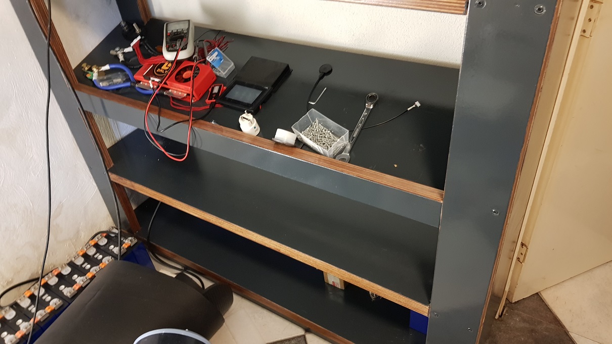
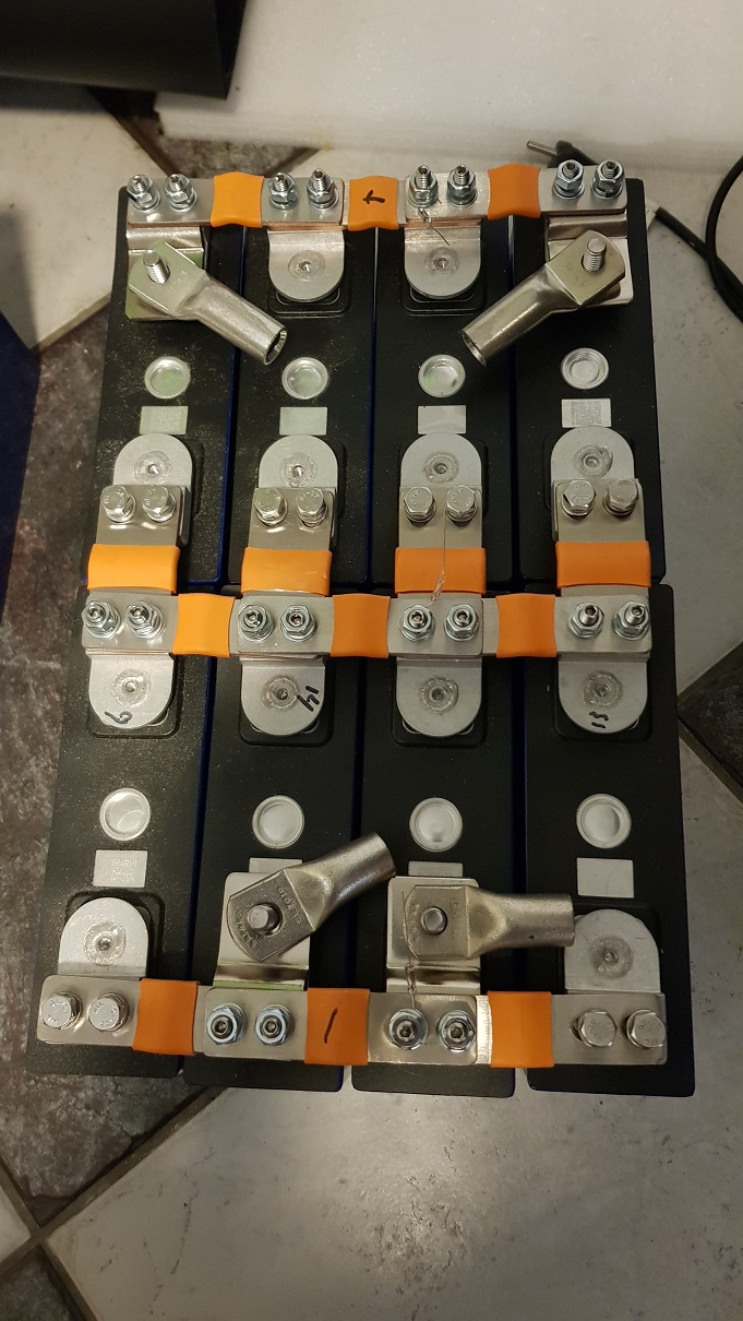
I made a small mock-up to see if my plan would come out as I expected. I think it does but before I put it together I want you guys to shoot at it in case I overlooked something!
Here is the battery. The mock-up is 4p2s but the end result will be 16s as you understand.
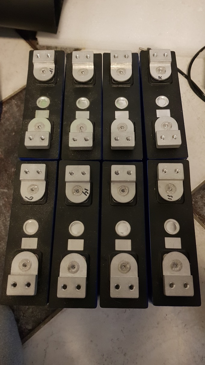
There will be 8s on the first shelf and 8s above it on the second shelf. First I screwed in the studs on the places where the busbars are 2 or 3 thick. The screws that came with the busbars are not long enough for that in my opinion.
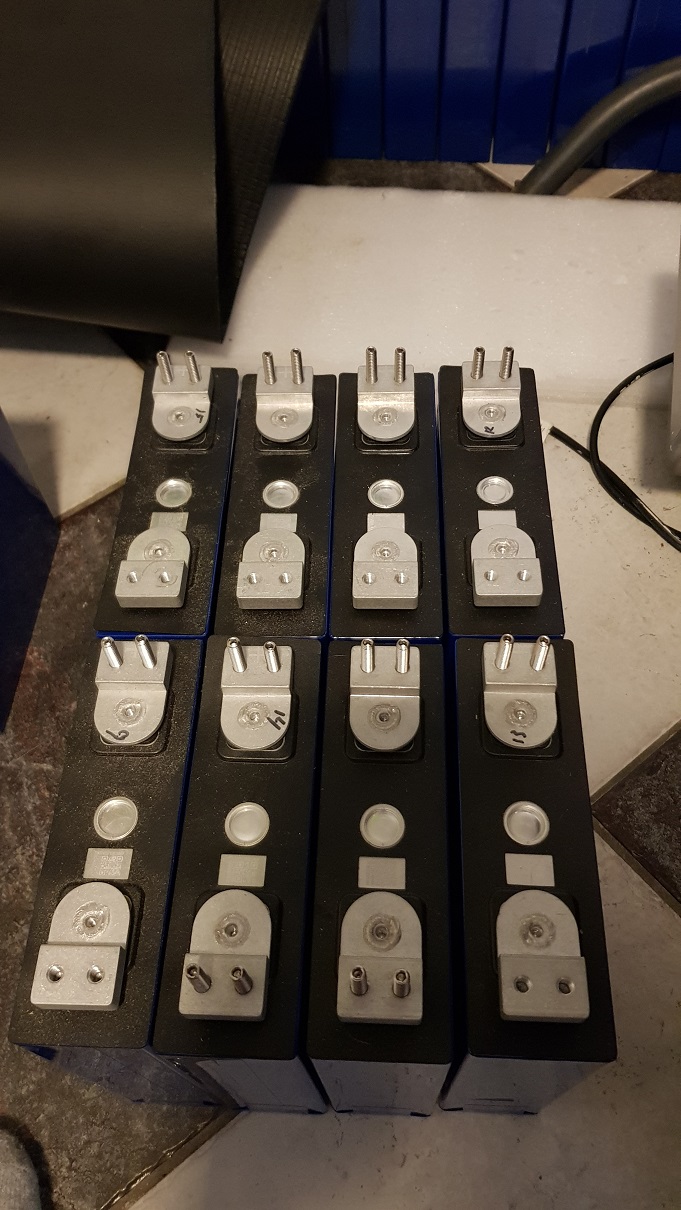
When you look good you can see the places where the BMS leads will be connected. These are 5A fuses. BMS is capable of balancing 200 mA and there will be an active balancer connected as well that can do max 2A. What do you think of this. Don’t be gentle, shoot!
My only thought here is that with a long link between some of the cells, you may get erroneous cell voltage readings on cell 9. Most BMS’ have a sensing wire to the + terminal of each cell and they measure the voltage (for example) from cell 8+ to cell 9+ as being the cell 9 voltage. Since you will have a long wire from cell 8+ to cell 9-, any current into or out of the battery bank will cause a voltage drop in the wire which will affect the cell 9 voltage reading. Other than that, the mockup you did looks really good.
Hi Stanley, yes you are right and I’ve been thinking about that. The wire will be two times 70mm2, 50 cm long. Max current will be 100A per wire and according to the Android Victron toolkit this will give a 0,1% voltage drop (3mV @ 3 volt cell voltage) so I’ll give it a try. If it is not enough I can double up to 4x70mm2 if I want but I don’t think it will be necessary.
0.1% at max current is way more than acceptable, and if your balance wires are on either side of this loop any volt drop across the loop would be excluded from presenting as an “out of balance” cell to the BMS anyway.
It depends on the application. Regulation-wise I’ve seen up to 5% being quoted as acceptable.
Opinion-wise for myself, I’d live with 2% and strive for 1% on a conductor run.
A lot has to do with the duty cycle and the cost.
Long runs are expensive, I’d be inclined to look at using a solution at a higher voltage.
Short runs like busbars, I’d use thicker copper.
If my current peak was vastly higher and shorter than my typical current and doing something about it wasn’t cost-effective, I might choose to accept the losses.
(Obviously, any conductor will be rated to carry any current peak continuously).
It depends, all these things are compromises, money spent in one place means doing without it somewhere else.
I’d think there are two things you are concerned about. The one is that you lose energy when a cable heats up (due to internal resistance) and of course you want to limit that. The other is that the voltage drop screws with balancers and other measuring equipment. So the energy-loss question you will probably balance with the cost of the conductor, and the other one becomes moot the moment you start to exceed the normal calibration error there may be in whatever the measuring devices are.
For cables external to the battery, 2% is good enough (for energy loss purposes vs cost) and 1% is preferred (for measurement/calibration). But inside the battery the rules will probably be different. 1% Would probably be way too much