Balancing Li-Ion battery packs is essential.
I bought many replacement battery packs from a large hardware chain at marked down prices knowing I could get value from these.
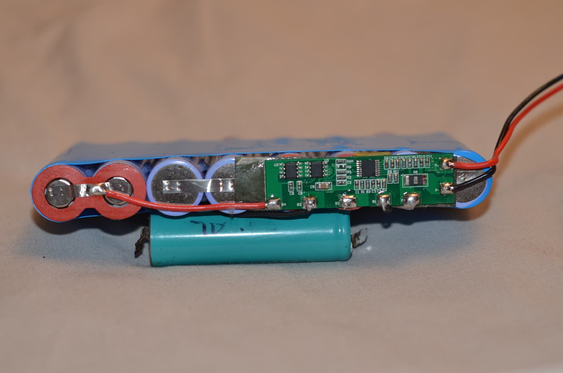
The BMS didn’t have a balancer so the packs would lose their capacity as one cell would have a higher voltage than the rest (and another would be at the low end).
And this imbalance would never correct itself!
The manufacturer presumably thought a balancer wasn’t required…
Exactly. One thing I perhaps should have mentioned, is that over time the cells also degrade slightly differently, so the balancer also extends the life of the pack by keeping their top ends in the same place.
Technically, if you started with cells that are very well matched, and you balanced them when you assembled the pack, you can get away without a balancer (just add a protection board to avoid fire) for quite some time. Until you cannot…
So again, this is why I don’t see a point in balancing in the middle (unless there is a massive delta). You’re not adding to the objective, namely to get more life out of the battery. Quite the opposite, it wastes energy.
I can see a point in balancing at the bottom, perhaps to get a bit more juice out, but I can also imagine that if you do both top- and bottom balancing, it will start working against each other. Once bottom-balanced, the next time you want to fully charge it, the cell with the lowest capacity is going to fill up first, again leaving you with the opposite problem.
Therefore, much better to pick one, and stick with it ![]()
The old saying goes: Simple is better than complex. Complex is better than complicated.
1 Like
Ditto. Pick one or it causes some drama. The top is also where the cells can be damaged due to too high volts. If cell volts are too low and the BMS/inverter switches off in any event to protect cells, so little risk of serious damage.
Titbit:
Balancing badly unbalanced cells when discharging helps quite a bit to get the bank in line faster.
Balanced when discharging on a balanced bank, I saw what you say, “start working against each other”. @Phil.g00 said the same. But I had to verify even though I trusted. ![]()
@plonkster you are now so talking my “language”. The middle balancing, as Andy also saw, using “Delta” more … Delta should be the trigger for balancing, starting anywhere it exceeds the pre-set value, not just on the volts at the top … too late.
BMS’es can be set to what Delta to balance to, starting if the cells differ by like 0.005v … so there is that too. But that is quite inefficient when charging.
Now one can set the difference to like 0.050v for example, but then at the top, the difference is too big, and way too late, will work against one. Hence the idea: If Delta is hitting like i.e. by 0.080v when charging, drop the charge amps. BMS will then still aim for 0.005v or whatever setting it is set at, to balance the cell difference.
I think that the delta should probably be voltage-dependent.
Lower down, a larger delta should be used. Higher up, a smaller delta could be used.
Below 3.4V, I think a 100mV delta is a good signal that you need to balance. Above 3.4V, I’d say more like 50mV at most.
But those aren’t the only factors anyway. If you have big enough bypass hardware, you can start later. If you have really small bypass/bleed resistors/transistors, then you need a LOT more time to get the energy distributed, and as a result the temptation will always be there to start earlier, or with smaller delta values.
If for example, you have a balancer that can bypass 2 ampere… You can put a 2 ampere charge current on that thing and probably balance it within two cycles tops ![]()
Delta is voltage dependent? Difference between min and max cell, ja?
And that is EXACTLY why I will get a NEEY balancer one day … 10a balancing if memory serves. BMS does BMS (protection), and NEEY does the balancing.
Balancers generally speaking are in mA as you say. Due to costs.
As time goes by, newer BMSs, I will bet, will have bigger balancers as experience is gained during the the 10-year warranties.
Jip.
If Delta is 100mV, drop the charge amps. When the cells hit >3.40v, normal balancing takes over, charge current stays low if not within ±0.010v Delta. The sooner the cells fall inside the BMS setting, the sooner the normal charge amps setting can be resumed.
It WILL have an effect on support … why is my system not performing at 100% settings throughout?
The caveat with lithium banks. Get used to it.
Will help a LOT as the cells grow older, and are cycled more than once a day.
I have a way better solution for all this. And it can be done in software (in the BMS firmware).
Use a dynamic charge voltage. If you have a high cell, drop the charge voltage so that you don’t push your highest cell over-voltage.
Then put down the magnifying glass and leave the battery to balance itself. It will take a while… who cares.
Then you don’t have to limit charge current. There is a reason you don’t want to do that… it means wasted sunlight, and therefore lost money.
Yes, that is a better idea … just have not seen it working as well, yet.
But then I must also be honest … I had to balance faster.
So yes, dropping the volts is definitely more eloquent, especially if you “catch it” before it becomes bad … dropping charging amps is the abolute last resort.
BMS manufacturers, most if not all, cannot update their firmware on existing banks.
So if I may suggest, Victron must deal with that. Get the Delta between the Min-Max cells from the Cerbo, and work it back to DVCC settings and drop the volts if Delta is as we talk, user-defined even better, >0.100v. If >0.120v, drop the amps too. If <0.020v, back to normal settings.
Oh I have tried that. There is no way to get it stable, for all use cases, for all battery sizes, etc etc. You have propagation delays in the system, the BMS might only send you those diagnostics you rely on every 2 seconds, then it takes another while before the hardware reacts… in the mean time that battery has shot way past the voltage it asked for just a few seconds ago, alarms are blaring, users are upset… and now I have to maintain the monstrosity I built because people rely on it.
Nope. Lower your charge voltage and go away.
![]()
If that can happen automatically, dropping the volts, then it is a “huge step for lithium banks”.
Although I did say that …
There are some caveats to “dropping the volts”. Always remember that while you bunch of saffers who are not allowed to feed into the grid can drop a charge voltage like it is hot… without any consequences… I cannot do that.
When someone selects the option “Feed excess DC-coupled PV into the grid”, any large drop in the charge voltage sends the Multi into full “dump it all into the grid” mode.
Therefore, you have to filter your charge voltage through a kind of low-pass filter.
Make that filter too aggressive, and the battery goes overvoltage.
Make it too fast, and the Multi constantly feeds energy into the grid when the voltage is lowered.
And here comes the kicker: The filter depends on the battery capacity. Big battery can have a slower filter.
In the end it turns into a big NMJ: Not My Job.
Then make the option disappear if feedback is enabled. ![]()
Maybe a dealer reads all this … and they take it further, as you said, follow the proper channels.
Simple is better than complex. Complex is better than complicated ![]()
A complex voltage-adjusting algorithm that is needed only for the first month or so of a battery’s life… but comes at the expense of maintenance and support… is a monumental mistake in my opinion.
That’s why the DVCC setting for lowering the charge voltage exists. Simplest solution that works ![]()
Burst out laughing … Simple can become a complicated Complexity.
I’ll wait, not the first time either, as it can take a few years of waiting for the “hard-cycled” SA banks to get older, and more unbalanced.
No skin off my nose. I have full control over it all with a Neey out there waiting for a new owner to boot one day. ![]()
Edit: As I always said to the developers …
Don’t open that can of worms. Nope, just don’t.
Other times, people, we need to open that can of worms now … it is time.
The trick is to know when is the right time to “feed”.
I don’t think that is going to happen. Unbalance is a thing in new batteries, because the factories push them out the door fast, with a set of “good enough” cells. Which is perfectly fine, the BMS will resolve those issues.
I think what people miss, is there are two ways of doing it, two ecosystems if you will. One is voltage-control, the other is current-control.
The Victron environment somewhat heavily favours voltage control. Put an unbalanced battery into the wrong environment, and it will have teething issues. That simple really ![]() But once it is over that… that old age degradation is slow enough that the slowest of slow balancers will keep up.
But once it is over that… that old age degradation is slow enough that the slowest of slow balancers will keep up.
“Thousands” of batteries on Victron systems … there is that too.
We’ll see. I can be wrong.
Over and out.
This comment was made a year ago but I’ve responded in this discussion:
@plonkster commented “4 LFP cells in series, so you would expect it to be between 12.8V (3.2V) and 14.5V (3.65V). Ideally these batteries should be kept under 14.2V of course”
I’m more familiar with the Li-Po cells which are fully charged at 4.2V
I see that non adjustable LFP balancer PCBs balance at 3.6V per cell: Other Electronics - Battery Lifepo4 Protection and Balance Board 4s 14.4V 18A **LOCAL STOCK** for sale in Cape Town (ID:592448252)
What is the reason for 3.55V per cell (14.2V) ??
It is safer, with more “headroom” left, as the cells are effectively fully charged at 3.55v.
The reason is that above about 3.45V per cell, there is very little additional storage to be had. If I recall, it is less than 1% extra. Above 3.55V per cell, it is even less. A proper LiFePO4 cell can be pushed safely to 3.8V, but to what end, an extra 0.1% capacity? Why bother?
And as we all know, longevity is improved if you stick lower down.
That’s why 3.55V per cell is more than ample. You want it just high enough that balancers can do their job, and not much more.
2 Likes
Thanks for this comprehensive reply. These details do matter and it’s good to know the reasons for them! :