So the suggestions are:
@Phil.g00 of:
Charging current of 0.33C: 150ah x 0.33C = 49.5a
Bulk/Absorp/Float: 3.285V/cel x 16 = 52.56v
Discharge of 0.2C: 150ah x 0.2 = 30a
Ps. My BMS starts balancing at 3.2v - can set it to any value.
@plonkster of:
Bulk/Absorp/Float: 3.45v x 16 = 55.2v
@TheTerribleTriplet
No, I did not say that at all, my numbers are wrong.
A) Because I equated discharge curves to charge curves. (which I said is untrue)
B) Because I googled some random curves off the internet. (They are not applicable to your cells and I have no idea if they are to be trusted).
C) I have no idea of your max charging rate or typical loading.
What I did was demonstrate what I would do if I had curves specific to your cells, which I don’t.
You must obtain/plot your own curves at your own max charging rate and typical loading rate and use the same technique.
We are talking tenths of a volt here and it really makes a difference, so by no means take my numbers as gospel.
1 Like
As I mentioned, one really needs to have a charge curves at your maximum charge rate setting and a discharge curve that reflects your average usage pattern specific to your cells.
These can be plotted easy enough, but I think with A grade matched cells manufacturers supply cell specific documentation.
As you have noted tenths of a volt makes all the difference.
“There be dragons” either side of the flat, best not to sail too close.
1 Like
I’m going to run for a while on 3.45v per cell with 60amps charging the 150ah bank.
Lowest SOC of 80% till I’m happy cells behave again, then back to 30% SOC.
Hi,
I have exactly the same problem…
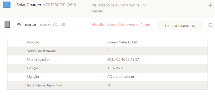
The ET112 + Victron RS485 meter / USB cable has no problem (I tested it with the Carlo Gavazzi software), but the energy meter is not found by the Venus GX.
Any progress in correcting the problem?
BR
JDuarte
Have you rebooted the Venus?
1 Like
Is that within the context of this battery driver, or separately? I don’t know about the issues with this driver. I suspect (but someone else will have to prove it) that the current version breaks the detection loop so that IF you have this serial BMS driver installed, then it MAY cause other hardware not to be detected.
From a Venus side… that issue I alluded to earlier was solved years ago. And if it is broken outside of the context of this thread, then you need to ask for help elsewhere, eg at community.victronenergy.com 
1 Like
I think this is something else and not the driver. I assume the RS485 is to connect to the ET112 and not a serial battery?
1 Like
Yes, ET112 is missing since first reboot with serialbattery driver installed.
Correct Louis,
The ET112 Meter is connected with RS485 to USB cable, and the LLT BMS is connected with RS232 to USB Cable.
Booth are connected into USB ports of Venus GX. I have a second GX (only for LAB testing) and the behavior is the same.
Can you give us some details on these cables. Are you using Victron cables, or after market cables? If so which chips and do they have unique serial numbers?
Also I assume you are using the V0.3 release?
Thank you Luis for your interest.
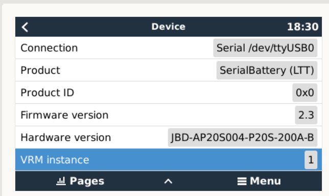
I´m using 2.3 firmware from github.

When I connect the RS485 cable (original Victron) the RX / TX blinks for 1 or 2 seconds. After that it only has the red LED (power) active.
In the RS232 cable from the BMS I have already tried it with a normal FDTI 232RL cable and with the USB to VE.Direct from Victron but the behavior is the same.
In your driver I just changed the minimum and maximum values of the batteries (I have LG Li-Ion from a zoe pack) and the respective charge and discharge current.
It looks like the cables are with the same address
That Firmware version is your BMS firmware 
There is a beta release for V0.4 that you can try that stop/start the driver differently that might improve your issue. Give it a try.
Those FTDI chips/cable you have look fine. And the USB ports are different also (0:1.1 vs 0:1.3). If you got the cable with your BMS they normally are fine (not fake chips)
That is fine.
I am aware of this thread since yesterday, this is exactly what I was looking for! I have different LiFePO4 batteries 8S and 16S with dumb BMSs from Daly, smart BMS from Daly, ANT-BMS.
First I thought about a selfbuilt RS232/RS485 to CAN gateway to connect the BMS to the Victron CAN-Bus, but your solution works without extra (proprietary!) hardware and this is much more elegant!
I am about setting up a Venus system on a raspberry Pi this week and am willing to give your driver a try on this (as I do not want to disturb my running system on a Venus GX).
As far as I can see from your code and the ANT-BMS protocol description, the protocols seem to be (more or less?) identical. Requests and answers look identical to me. Did you ever try if it works with the ANT out of the box?
PS: I have also ordered two BMSs (8S and 16S 100A) from LLT as well as some FTDI USB-RS232 and USB-RS485 converters. So I hope I will be able to test all this within one or two weeks now …
I have not had reports from anyone that tried the ANT as the driver is now, so give it a try.
There are some small differences that I expect would make it fail. The checksum looks to be calculated differently which should then mean any command would be seen as incorrect.
Do you have the actual protocol document? It would be great if you could upload that to the github ticket as I currently only have code snippits for the ANT to work with.
Hi Louis,
thanks for the fast response! The documentation I have is an excel sheet with some protocol details which I downloaded from here [GitHub - Sgw32/BMSCtl: ANT BMS (antBMS) control panel on C# with UART capability. I hacked protocol and reverse-engineered it.].
And, checksum, at least the requests look exactly alike. I read in your lttjdb.py that the general read command you use for the LTT is “\xDD\xA5\x03\x00\xFF\xFD\x77” and the ANT doc says “DD A5 03 00 FF FD 77”, so the checksum seems to be the same.
That general read is used to make the connection. If they are the same then give it a try. It should connect and then we can see what other data will come through. It would be great to get a report from someone that has an ANT.
I will keep you informed. Ordered raspberries, converters etc. yesterday, so I think I can start end of the week!
BR, Jörg.
PS: the Xiaoxiang app does not work with the ANT, it finds the BT device but will not connect …
1 Like
OK, big disappointment here! You can call me stupid, but I only just found out that my ANT-BMS (like all others?) does not have a dedicated UART port! The only UART port seems to be occupied by the (internal!) BT module. I thought that the LCD interface had the double function as a UART port, but this does not seem to be true (still have to find out if this is so).
Only possible solution seems to be to desolder the BT module and connect to the solder pads directly. But this means that mobile phone connection will be lost …
This is possibly the reason why noone else has ever tried to use your solution with an ANT BMS!
I will get a second ANT BMS within a few days and will possibly make the solder mod to the first one. This is going to be used in a remote location where the mostly used interface will be the VRM remote console, so that the missing BT will not matter that much (but setting/changing parameters is much more comfortable via BT!).
BR, Jörg.
.


