Very understandable.
Thanks for letting us know.
I am very much looking forward to testing.
1 Like
Hi @Louisvdw, was reading your write-up on Github and spotted this…
- Can handle batteries with from 3 - 32 cells
I have the Daly BMS hooked up to my 16s4p battery, 64 cells - does that “throw the cat among the pigeons”?
No rush, understand you busy with paid work…
Thanks
Graham
This is actually the amount of cells that your BMS can handle. Some of the LTT/JBD BMS models can handle many cells and their protocol is for up to 32 cells. This reference that the driver can address up to 32 cells internally (for the LLT/JBD battery)
If you have 4x Daly BMS that would be multiple Battery banks (4 banks) which is another feature on the todo.
Your Daly does 16 cells. But currently the driver only handles 0 Daly cells ![]()
Hi, I love this project! I found details on it from the Victron forum. I was wondering if you’re able to enable/disable charging/discharging from the battery via the Victron inverters and MPPT charge controllers based on low/high cell voltages being reported from the BMS using this tool?
The reason I ask is that I’m planning on putting together a LiFePO4 3p16s 280Ah battery hooked into 3x 5000VA Victron MultiPlus 2 inverters and a 250/100 BlueSolar MPPT and I’m strugging to find a BMS which can handle the charge/discharge current (approximately 350A discharge and 250A charge continuous) I’ll need.
If charging and discharging cannot be disabled/enabled, can you advise what an alternative solution might be? I’ve seen some information about using relays to achieve the same function for higher current loads? Ideally it would be great to do this via Venus OS though.
Thanks in advance for any help!
John
Hi John,
Just to make sure I understand. When do you want the charging/discharging to stop/start?
If this is just when the battery is empty/full, then this is in there yes.
2 Likes
Have a look at the Charge current control management (CCCM) in the help. This limits the current when the battery is either getting full or empty. Currently this is only for 1 bank, but the next item on my list is multiple banks, and CCCM will be an aggregate of the banks. So if one bank is full the charge/discharge limits will be reduced to show that.
![]() actually, I had a senior moment there, this is a 16 cell battery - eish
actually, I had a senior moment there, this is a 16 cell battery - eish ![]()
1 Like
![]() hehe.
hehe.
Yes. This is all about the BMS’s cells, and not how many cells you added to parallel to the BMS. Only if the BMS know about those cells separately can the driver do anything with them (separately). If you have the cells in parallel the BMS will see them as one.
1 Like
Thanks for your response Louis.
Yes, I’m wondering if one of the cells in the battery is reading at the high voltage mark set that the GX device will tell the inverters and MPPT charge controllers to stop charging the battery. And the same if one of the cells in the battery is reading at the low voltage mark that the GX will tell the Victron inverters to stop dischaging/using the battery. Is the help guide on the github page?
The help guide is the Github page, yes.
Yes, the driver will handle this for you.
The BMS has flags when exceptions happen. These notifications are then passed to the GX device that will act on them.
There are 2 levels of this.
First the BMS will give an exception and/or set the flag that it is not excepting a charge (or discharge). These exceptions normally happen when a cell jumps higher than the max cell limit (or below). So this level is managed by the BMS and the driver just sends the notices to the GX.
The second level is the CCCM feature. This is something that the driver manages and it will set the charge/discharge limits depending on the State of Charge (SOC) of the battery. In short the closer the battery’s SOC is to the min/max limit the more the discharge/charge will be limited.
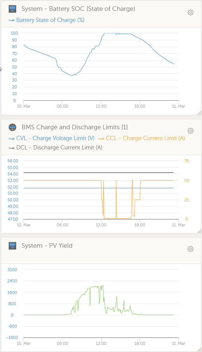
Here is my graphs from yesterday. Just after 12:00 the batteries was reaching full charge (top graph), so the charge limits was lowered (orange line in second graph). This ment the MPPT charging was also limited correspondingly (green line in bottom graph) to only produce what power is consumed without charging the batteries.
2 Likes
Thanks again for your help Louis. Can you see individual cell voltages from the GX device with your driver?
Also, I just want to confirm that the BMS will send commands to the GX to stop charging/discharging based on min/max cell voltages and not the overall battery voltage?
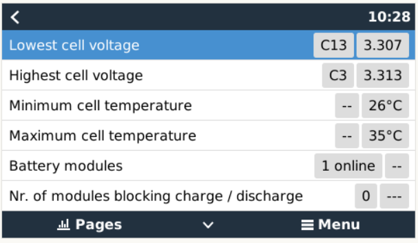
Only the lowest cell voltage and the highest cell voltage and which cell that is. (This is what the GX has space for). See top of image below.
Yes it does. But it depends on what your BMS settings are.
Lets assume you are talking about the LLT/JBD BMS. If your BMS setting for max cell voltage is 3.65V and any one cell go above that voltage, then the BMS will raise a cell imbalance alarm and also set the allow charge FET to false. The driver will raise the cell imbalance alarm in your GX device and also set the allow charge to false.
In the Remote Console you will see those alarms, but more importantly under the Battery → Details you will see Nr. of modules blocking charge 1 instead of the 0 as in my screenshot.
The BMS will be doing balancing on that cell and when the voltage has lowered below your release threshold (also set in the BMS) the charge will be opened again.
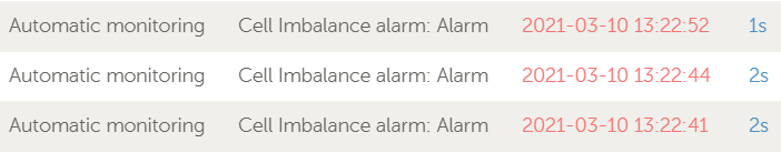
This is how the cell imbalance looks like in VRM. I don’t have a screenshot the show the blocking charge.
2 Likes
Been struggling to figure out why my system under performs i.e. stuck on 4amps max charge.
Then I saw why.
- BMV SOC
- BMS SOC
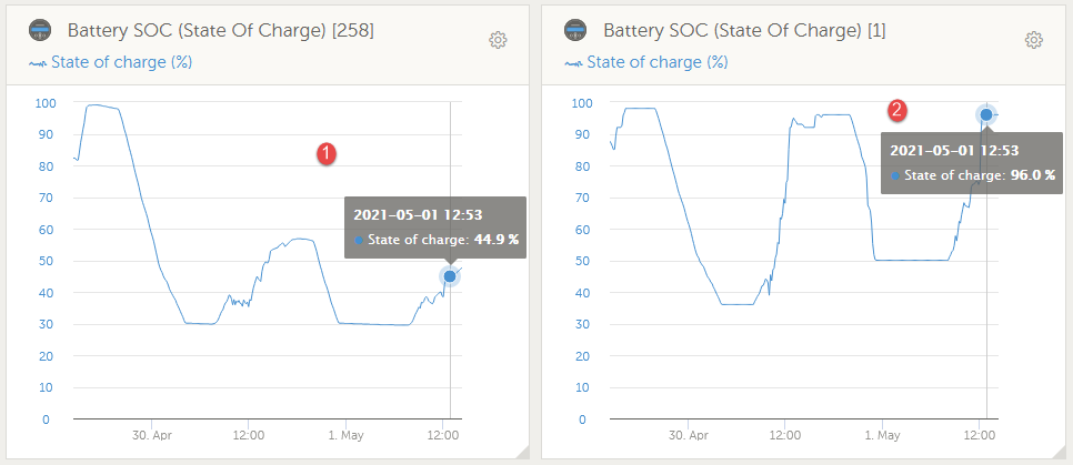
The system sees 96% SOC from BMS, whereas the BMV still has not seen enough charge put back to register 96% SOC, which I know is true, as the weather is a bit under the weather last day or more.
Had to reset the BMS. Sorted the SOC discrepancy.
"Reset" BMS: Went to Parameter settings and saved them again. BMS resets.
Ps. I ALWAYS get the fringe issues. (facepalm)
Which do you trust more China BMS or Victron BMV 
Why the huge difference in the Amps IN between 10:30 and 16:00 on the 30th… looks like the BMS is seeing alot more power input… do all the MPPT’s go through the BMV?
1 Like
Upon further investigation, two cells out of 16 decided to get over excited …
1 Like
I must admit I am not to keen on the DIY battery bank route… sounds like lots of work and risk… 
Depends on a few factors, the biggest one being if one follows the brand names settings on ones DIY bank or if you are pushing the envelope a bit … I WAS pushing the envelope at 3.5v per cell instead of 3.45v.
DIY banks gives a LOT more options … I’m not worried about these small teeny hiccups, I’m learning.
For me, the fact that I can alter and change and learn, at half the price of a brand name bank with no access, makes a HUGE difference.
If this was a brand name bank I would have had to wait for Monday to contact support.
EDIT: Less I forget, I also alter some settings in Louis BMS/Venus interface. 
Agreed boet: But you wouldn’t have been pushing the limits with a brand name bank… Oh wait… this is @TheTerribleTriplet… retract that…
1 Like
Never … not me … here, hold my beer … ![]()
Yeah, seems to me 2 cells, one slightly bulging, are the two culprits.
*$#&%&@^!!!