That is not a test. ![]() … “under load”, I said.
… “under load”, I said.
That infamous DC Ripple …
The first time I learned about this was when a 250/100 “took the shots like a trooper” when a badly balanced Lifepo4 bank had the BMS switching off time and time again.
EDIT: The inverter was at the time it happened, running at like <300w, the batts where “full”.
Till the MPPT said the last time when the BMS switched off: “Enough now already!”
MPPT had to be replaced (2 weeks old) … and the battery bank was returned/refunded.
Victron MPPTs can “take it” … till it does not.
When my MPPT gooi’s like big watts (5kw i.e.), volts far within specs, I would NEVER just flip a switch to switch it off. Nee o magtag. Common sense says that is a very, VERY, bad idea.
It is one thing to adopt a practice that is inherently safer, which I happen to agree with.
It is entirely another to deny yourself the protection of cabling, to prevent yourself from accidentally not following your own policy.
Indeed, in terms of safety you are just fine and I know several good and well known installers who will skip this item and use only the breaker in the battery. I would not worry about this.
Because this is an isolator and not overcurrent protection, the rest of what I wrote here might not apply, but here goes anyway.
In a system where the battery is grounded on one side (the negative typically), you will have a fuse only in the positive line, and it will be AS CLOSE AS POSSIBLE to the positive pole. Open the bonnet on your car, and you will most likely find a fusible link built right into the positive terminal. In a setup like this, any ground fault from the positive side causes a large fault current to flow, and the fuse in the positive line blows.
But in systems that are floating, you can have a ground fault on either side, but nothing happens until there is a second ground fault on the other side. In such systems, you would then fuse both sides, so that you have overcurrent protection on either side.
But that is for overcurrent protection. Not isolation. So while the grounding of the battery would normally play a role in this where overcurrent protection is involved, I am unsure how it applies for the isolation requirement.
DC ripple doesn’t happen when the MPPT loses its connection to the DC bus. It happens when the Multi/Quattro (or any other LF design inverter) has insufficient storage capacity attached to it (eg, when BMS disconnects cells from the DC bus) and the natural 100Hz ripple on top of the DC becomes unmanageable.
I had a system previously where there was a DC breaker on the battery side of my MPPTs. One of them used to trip a few times a week (because I was running it above 80%, see). Nothing ever happened to the MPPT.
But… there are MPPTs that don’t like that. Earlier models of the Microcare units would blow up if the BMS disconnected the cells from the DC bus. The voltage would spike up to over 70V and take the one power supply unit with it. For this reason, it is good practice to not disconnect the MPPT from the DC bus while it is under full power. You can still have a large voltage spike. While the equipment can take it, why do it if it costs extra money and adds nothing?
Just use a Lynx distributor, and install a fuse that protects the cable for each mppt and for the inverter. Done.
You are 100% correct … it is not a ripple if suddenly an MPPT has nowhere to send the watts when the battery disconnects.
Or like the batts are off, the inverter is switched on, and the MPPt happily starts up again. Been there, done that. Groot skrik.
Context:
But when that inverter, due to BMS switching off, with a resultant ripple, now that is epic to watch the faces when the MPPT gives an error, and the repairer says “Ag my f#($*%, not again! Just send it in. (sigh)”
FACT: Switch off the panels first, then the MPPT. It is the “right way”.
I am not an engineer…
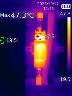
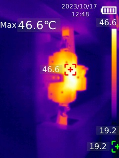
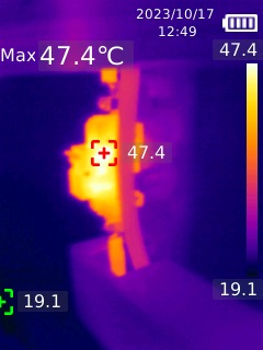
apparent hotter “body” of the MCB vs the terminals is not necessarily indicative of a problem:
The heat that is generated from inside the breaker comes from the contacts and the bimetal, which are typically the hottest parts within the breaker, and the temperature in the current path gets cooler the closer to the bus or cable, which function as heat sinks. Therefore, the sides or bottom of the breaker can be hotter than the terminations.
.
.
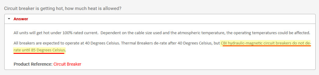
The CBI breaker as per OP is not a bimetal/thermal magnetic breaker but a hydraulic-magnetic circuit breaker.
longer with reference to the CBI application guide:
*[slashes “/” indicate parts where source material was cut/omitted]
UL specifications are:
lastly, borrowing from the folks at ABB (“ABB circuit-breakers
inside LV switchboards)”, this might be a useful reference as it is adapted for circuit breakers etc. in enclosed switchboards:
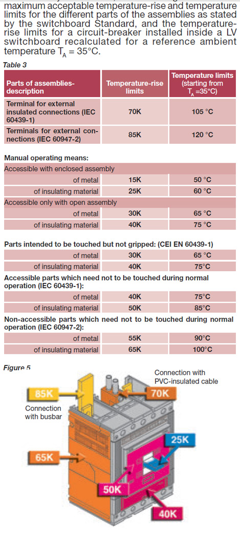
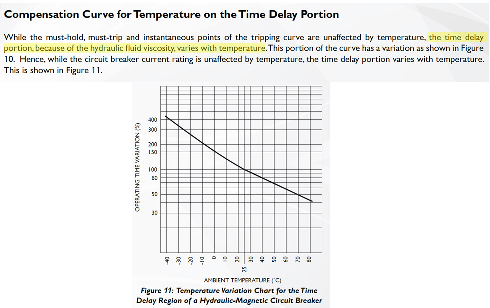
Thermal derating curve, nit for a thermal breaker but to see the temp curve for derating.Figure 11 and UL specs both provide some insight.
Groetnis
Thanks. I’m not an engineer either. I assumed the breaker will be the usual thermal arrangement.
Your message made me think a bit and it is rather difficult to think of all the permutations of what could happen in fault scenrios so I made a crude sketch-up hoping to get my thoughts in order. Unless my comments on attached sketch is way of the mark I am of the opinion that fusing both the positive and negative is only for isolation purposes and has no benefit when it comes to overcurrent if the system is ungrounded which is the case in most systems I’ve seen.
My thinking currently is that from an overcurrent perspective the Freedom Won’s built in breaker on only positive is adequate and if I have to break both positive and negative according to regulations it is only applicable from an isolation perspective.
Please feel free to scribble on my sketch, as mentioned I could be missing fault scenarios.
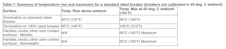
@Sarel.Wagner great insights thanks! So from UL specs, my measurements are still well below the 85 deg C max for handles knobs etc. non metallic. That being said the discussions above steered me in the direction of fusing instead to remind me not to break MPPT from battery under load and always disconnect PV first. As @TheTerribleTriplet the Mandalorian said, “This is the Way”
I also cannot really think of any way that an earth fault can cause an issue here. The DC breaker is inside the FW battery too, which means there is no exposed conductor between the battery and the breaker that can cause an earth fault.
Additionally, in my system I have a Multi RS where the manual specifically calls for battery negative to be earthed. With the breaker as close as possible to battery positive, and battery negative earthed, I believe the system is properly protected against a single earth fault.
But again… that speaks to overcurrent protection. Not isolation. Isolation is probably something that is done manually, during maintenance, or because resolving some other fault condition mandates it.
Some thermal images taken today, with the enclosure opened, segways nicely from your message