My main system consists of 3000W panels in two arrays, two Victron 150/70 MPPT’s, Victron 3000VA/48V inverter, all linked to Venus OS on Raspberry Pi.
8x150Ah SonX AGM’s going on six years.
Genny as backup for those crappy days. Totally off-grid.
Panels not optimally aligned to the sun. Winter only sees 1300W from panels on a very good day, but manage withe even that
I work in many houses on an established eco (off grid) eco estate. As people upgrade to newer 48V systems and Lithium batteries, I am the receiver of old systems.
Have 5000VA/24V invertwer, two Outback 3000VA/24V systems etc
I have connected 9x175W panels to Microcare 150/60 to Victron 5000VA/24V inverter.
Battery bank consists of one Willard 12x2V cells bank and three Trojan 6V banks configured to 24V.
All still good for my use. The panels here are super optimal for the winter sun…first rays hit them sq.
(my freebie system)
The two buildings where they are housed in is 60m apart, trenching wise. So laid a 6mm Sq armoured cable between the two with comms cables.
Son is a bit of Victron techno dude and we are going to connect the two systems together. 24V system has small usage draw is normally always full, thus it is to be programmed to send excess power to main system.
Also vice versa…all part of a large experiment.
I can then hopefully run my spray painting compressor earlier in the morning and reliance on genny becomes less.
Anyway, are we wasting our time and resources or will it work?
What pittfalls are expected?
To be honest, my eyes glazed over a little reading all that. You can certainly parallel the DC side, but probably not if the other battery is 60 meters away. You certainly cannot parallel them on the AC side if they are not the same model and size. It would be exceedingly unwise to parallel them if they are 60 meters apart. The VE.Bus comms runs at 2400 baud. Over 60 meters… I don’t think you are supposed to do that.
What you can do, is connect the input of the smaller Multi to the output of the larger one. That kinda sorta works when the grid is on. When there is an outage, the downstream Multi moans and groans (audibly) every time some largish loads starts or stops, and can even disconnect and reconnect repeatedly because it is not really designed to AC-tie with another inverter in this manner. So even this… not really advised.
In short, I don’t really see a way to make this work reliably.
What you could maybe do is run AC-cables from both systems to each other and install a battery charger on the other end. Then you can transfer surplus power (not very efficiently, but it will work) from one system to the other.
You could also do the thing they do in dual-battery car systems, with a DC/DC converter, but low voltage DC over 60 meters… nee man…
Probably better to sell all the batteries and inverters and buy a Fronius or other Grid Tie inverter to use the panels. Solis is cheap for the functionality.
Plus it can be networked - Fronius anyway (using UTP) back to the Cerbo (or GX) - 60m is fine for that.
An idea for your son, maybe it is relevant to your question.
I “heard” of someone who has a grid-tied 48v 5kva MPII system.
They also have a 12v MP 500va connected to Rpi with the Venus OS on it with a 100ah Lifepo4 bank.
At night the main system feeds the entire house with like 500w.
The teeny 500va also “donates” like 100w to the house. (recharged with spare power the next day)
Because the main system has a Carlo as a point of reference to not feed back, it will slow down its draw on its batteries, if the house loads drop below 500w, as the 500VA MP has no current sensor on it.
And because it is plugged into a wall socket, one that goes off when Eskom load sheds, with LS, it will stop feeding back to the house AND avert the “moans and groans” noise @plonkster has mentioned.
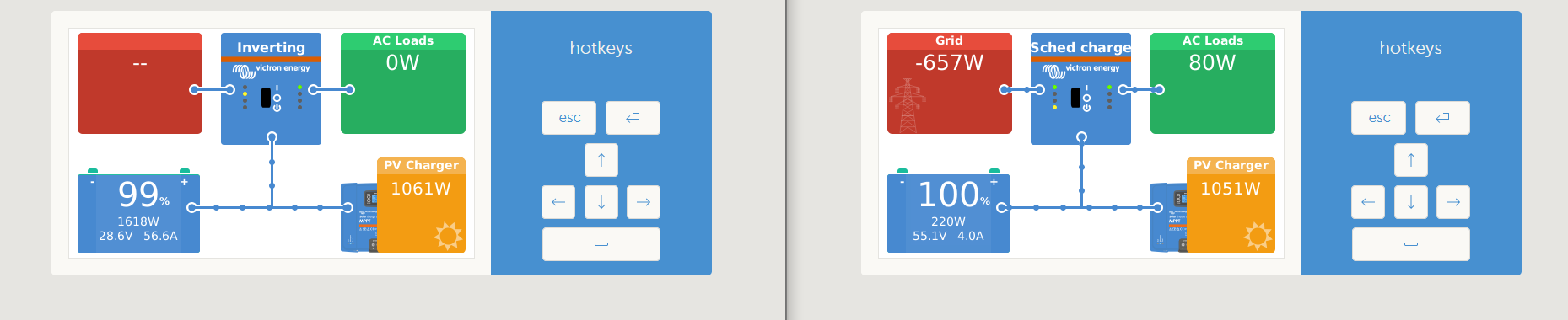
We got the two disparate systems set up. Power can be send both ways and it works. Lots of fine tuning to be done.
But secondary system currently helps main system to get to ‘float’ and then excess from main system is fed back to secondary system to get it charged…really this grid feedback thing.
I have two totally separate systems, each with their own hardware, panels and batteries. And totally off grid. Each has own Venus OS on a Pi
I wanted to make the one with the deep cycle LA’s my ‘Eskom’ or grid. Never thinking about feedback.
So thus the 60m Ac 6mmsq cable between the two. Ac out and AC in.
So secondary system gives main system a boost in the morning to get full and then the main system sends excess back to secondary system to get full.
We used a New Zealand grid code as it gave best options.
Main system runs my woodworkers shop as well, so set a max of 2000W draw on 3kVA inverter on the ESS and rest then comes from secondary system.
Works well when the coffee machine and toaster is working at same time, yip I can do that now.
This is termed as a micro/mini grid if I’m not mistaken??
PS: How do the residential complexes that have PV systems in each dwelling (and one connection to the grid) manage the power distribution within the complex?