Submitted an application to CoCT, as per SANS regulations, they require a DC isolater, on the battery circuit, I thought a fused disconnect eg Keto would suffice, any thoughts on what I should do/use
That should be fine, surely!
These are as good value as I could find:
This is likely to handle plenty amps. What have you rated the fuse at?
@Tariqe what symbol did you use in your drawing for dc disconnect?
Ja nee wragtag.
I have the same Keto fuse on pos and neg.
You cannot disconnect the battery from the inverter/MPPT more than that.
Interesting to see what @Rautenk says.
I have recently applied for permission to install a PV hot water system from CoCT. This is no big deal since it isn’t connected to the grid. However they wanted an electrical drawing with the application. I contacted the supplier (Geyserwise) and they sent me the drawing I needed to submit.
They didn’t impress me with their motive for needing this information…
Geyserwise PV Waterheating System Dual MPPT.pdf (177.4 KB)
Does anyone have and is happy to upload an example of their diagram for COCT?
Suggestions for drawing/editing software programs also would be great.
Thanks
I use qelectrotech. The symbol I used is this one:
![]()
1 Like
@mmaritz I used Draw.io for my design. It took me a bit of time to learn it with my first design for my first house, But with the second house it went really fast.
I did my application for my SSEG at COCT and is registered with my setup.
Just clear it out for you guys, please don’t submit a drawing that you did in Windows paint. I had guys that asked me to check there drawings and then it’s a paint drawing they did them self. When you submit this, the administrator officer that woks with this stuff than needs to hand it over to the technician, will check the stuff and will reject if it’s not correct.
They getting more and more application every week and they starting to get the hand over it how a correct drawing looks like.
Here is a link from the city site that can help with some stuff: https://resource.capetown.gov.za/documentcentre/Documents/Procedures,%20guidelines%20and%20regulations/Embedded%20generation%20schematic%20drawings%20SK5276.pdf
And here is the new Feb update for Technical Standard for the Interconnection of Embedded Generation
1 Like
I am waiting for the technician as to why a fused disconnect is not enough, hope he comes back with decent answer, I have had three schematics get approved with a fused disconnect, but this is new…
i have used the same symbol as the guidelines suggest
A good question!
I’ve been waiting in vain for an electrical drawing package to become the de facto standard.
Alas this hasn’t happened. I thought Visio might get there being a versatile package but…
Regarding the symbols that are in the CoCT document: All fine and dandy but are we meant to regenerate these pixel by pixel in some obscure non standard drawing package??
I don’t like the way they got the drawings in that pdf. There are loads pointing in different directions and some of those symbols are not standard NRS symbols. Im surprized they dont ask for cable sizes on drawing.
I like to draw my electrical circuits in a top to bottom direction with power in the top and loads out the bottom same as I would wire it.
1 Like
The main DB board in my place would drive you nuts. For some reason the main breaker is on the far right, and then subsections of the house is wired left to right (with the RCD for that section to the left of the section). So I stuck to this convention mostly because I’m not OCD enough to do a rewire and I’m sure wire lengths will be a problem… but I too prefer top left to bottom right layout.
Probably because I’m a westerner who write that way…
Same this side with Top to Bottom and split the drawing with DC on the left side of the drawing and AC on the right side of the drawing, and show Neutral, Live, Earth, Positive and Negative lines in the drawing. Makes it easier to read then.
1 Like
just talked to the CoCT technician, he is ok with a Keto type fuse disconnect, he asked that I label the drawing as a “fused disconnect/isolater”
Some people are unaware of the MCB symbols differentiating between on/offload isolators and circuit breakers. I standardize on buying circuit breakers suitable for isolation.
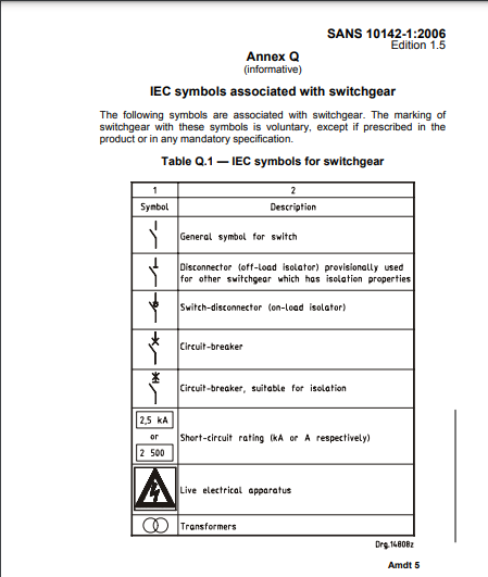
So we use IEC electrical symbols…
It is useful to know because even electrical suppliers may not always know and sell you something for the wrong application.
Some circuit breakers are unsuitable for isolation and some isolators are not rated to break load current.
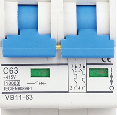
For instance this isn’t an MCB that can be used for isolation:
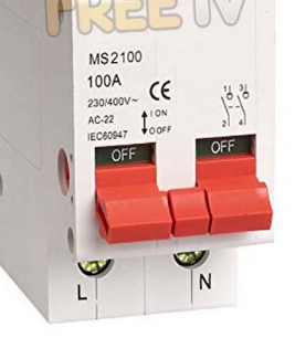
And this is an isolator not an MCB:
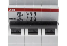
But this is an MCB that can be used for isolation.