Choosing Panels

Hi All,

I need assistance in fully spec’ing out a Sunsynk 8kw in terms of PV

I have large loads on both essentials and non essentials, and while they are balanced nicely, I am obviously looking to utilize my setup to its maximum potential within a margin of safety.

Loads are under control, and with some smart automation, I will not exceed what my inverter can supply for essnetial, and the rest of the heavy current items being on eskom where it will stay, I have no interest in going fully off grid.

I recently installed/upgraded an 8kw Sunsynk, and I am looking to spec it to the hilt in terms of panels.

I currently have a bank of 8x275 Canadian solar panels in production from my previous system, This bank will stay for now, and I am looking to add another bank within the next day or two, as I am expecting heavy stock shortages.

Therefore,
Bank 1 = 275wx8 to be upgraded to the same to make up the 10.4kw allowed on the inverter, so target ideally 5200w
Bank 2 = empty, target 5200w

For bank 2, I have been looking at adding in 8 to 10 panels, depending to fill bank 2, and then next year I want to replace bank 1 as well with a similar setup to get to my ideal of 10.4kw @22A, with say 15% to 20% headroom

If I spec for example, 9 JA 545’s, at 49.75Voc that is a total VOC 447.75, which exceeds the recommended 425v, while I know that is under rare conditions, there is no headroom.

If I look at the 8x620w Jinkos, that is a total VOC of 444v, which is also above that threshold.

In both these cases, I have plenty headroom on operating current which is around 13.5A, with spec calling for 22.

If I look at the Trina 575w, that has a Voc of only 46v, at 8 panels, that gives me a VOC of 368 and it has the highest current rating at 15A, I can maybe even sneak 9 panels…

So there is my answer… but I cannot find stock.

Freshtech has JA and a 450w Trina, Inverter Warehouse has Jinko. GoG has nothing…

What would you recommend to fill both MPPT’s to the max, not leaving anything on the table, but within a margin of safety and where I can actually get stock,
In general, ( but seek Sunsynk-specific confirmation), the voltage limit is a hard limit that must never be exceeded, and the current limit can be considered more forgiving.
MPPTs (Some?) offer reverse polarity protection, and that is the basis for the current limit. When you exceed that, the reverse polarity protection may fail. But of course, you only need reverse polarity protection if you swap the PV pos. and neg.
So assuming you get your polarity correct, the current limit is a broader recommendation that, when it is exceeded, causes the MPPT to clip its power output. Designing in a small amount of clipping can be a good thing and is by all accounts considered best practice in Australia. Obviously, vastly exceeding the current limit is inefficient, so it isn’t done.

See here for which panels specs are relevant to an MPPT and how to interpret your own:

The SunSynk limit is actually 500V, but the mppt range is 150-425V. Usually it just derates after 425V, but I don’t know what exactly the sunsynk does. Though if you can actually use the power, you will be closer to the Vmp at best.

There are many people that have 9 JA 545Ws on the SunSynk, they won’t go oven the max voltage that your inverter will tolerate, and they will almost never be over the 425V that it needs for the MPPT (because of NOCT)…

Thank you guys for the reply…

anyone running 18 of the JA’s 545… 9 per MPPT ?

1 Like

Sorry, that is what I meant 9 per MPPT, so 18 in total is a good config for the 8kW SS.

For clarity, the 10400W is (IIRC) the max the MPPTs can actually do, so if you have enough panels, and the batteries are charging and you have a load, you can actually convert that much power from the panels (though both the battery bidir converter, and the AC bidir converter has a lower limit, 8 or 8.8kW from what I remember, so you have to have combined loads to achieve that). I think you can actually overpanel a bit more than 10400W (probably by going with something like the 18A Canadian solar HiKu7).

Thank you so much sir,

Based on the advice, I have ordered the 9 JA’s and we are good to go.

I have a couple more questions, both banks in questions here.
Bank A is the new panels, Bank B existing and it has no earth protection on the frame. I added in an Beny 600VDC SPD wired to main earth of the property.

For Bank A, I have ordered another Beny, but I need to earth both banks.

Question 1 : Do I add in 2 additional earth spikes as the banks are far away from each other, and do I bond them together (earth), or do i bond all 3 (2 banks + house together)

Question 2: SPD placement - In my DC combiner board, I plan on two isolators, 4 fuses, and 2xSPD’s. However first bank is close, second bank is 40m away. I am not comfortable with nearly 500v in my roof without protection.

Therefore I plan to install another 2 fuses in the roof right by the panels for Bank A. Meaning bank A will be double fused.

Where do I place the SPD’s, is it OK if i place them at termination point, bonded to the house, or should the SPD’s be as close as possible to the equipment. I am worried that if I do it this way, I will introduce 3 differant earth potentials, and then things go poof.

Or am I just over engineering the crap out of this for no good reason

I’m probably the wrong person to ask this question, but I would go with an earth spike or 2 and bond all 3. (The amount of spikes would be determined by the impedance - keep on adding until you meet the requirement).

Definitely earth the existing bank frame (and keep in mind that a copper wire to each panel is probably required with the correct fastening method to ensure you pierce the anodizing (and it does not re-anodize itself).

The SPD should protect the equipment, so that’s where you mount it (because induction might cause a spike even though the other end is protected). Also preferably it should be rated for the max of the MPPT - 500V, 600V is better than nothing, but then you are placing a lot of burden on the MOVs inside the inverter, which should be treated like a warranty sticker.

You don’t need DC disconnects (as in -they are optional) because of the disconnect on the SunSynk, as long as it is installed per the height requirements. You also only need to fuse one of the wires per bank. I would install the wires in a metal conduit/sprag for safety as well as likely future regulations.

The double fuses might lead to headaches further on (when you or the next guy have forgotten about them), which is why I would avoid it.

But then again, I’m just some guy on the internet, so please don’t rely solely on my opinion.

For some guy on the internet, your advice makes a bucket load of sense I must say.

I know about the anodization based on research, so that’s spot on.

Also correct on the DC disconnects, but “while you are in there”, I like the idea of the DC disconnects and that I can target each bank, so that is a preference, not a choice.

Fuse both wires, just because, the fuse holders are actually cheap. As for the double fusing, good luck to the next guy in this place in general basically, as I have over engineered the crap ouf of everything, but we have been here 35 years.

What is exceptionally valuable advice however, is the metal conduit bit, which is a SANS requirement, so there I say thank you, much appreciated

What current value of fuses are you going to use and why are you choosing that value?
I am asking because I’d like to know where sufficient current will come from to blow them.

I decided on the 25A simply because the Inverter max spec is 23A per MPPT, and technically then the 20’s would be too small. I know its a tiny bit over,

Technically, I could have sized smaller based on the 14A from the panel that I have chosen… you are actually correct now that I think of this.

Think i should swap fuses ?

The ground rule is: You fuse according to the current capacity of the cable, or if there is another “narrower” path, then according to that.

I think for PV you then limit that to 125% of what the panels make, if I recall correctly.

In my experience, if you don’t make the fuse big enough, they tend to suffer a kind of heat-fatigue and fail. I think 16A fuses will do that in your case, so I would go with 20A fuses.

Your panels can only deliver Isc no more than that ever. They will be typically running around Impp.
Fuses are not an exact science. There isn’t enough to differentiate between those two currents. Coupled with the fact that fuses age and can suffer nuisance failures, and they take a long time to blow right on their current threshold.
I am saying that the second set of fuses at the panels will only be a headache and offer zero protection value.
The only possible source of high enough current to blow fuses is from the inverter. So we are not trying to protect the inverter (if it is back-feeding the panels, it has already failed). What you want to protect is the solar cabling to the panels, which is (typically) rated for 30A. So 32A fuses at the inverter on the PV side are rated high enough not to nuisance blow and still able to provide the protection of the cabling. (Usually, you would 25% overate the fuses, but you can go tighter in this case).
I would also say that many installations may even dispense with these fuses as this would be a rare failure mode.

2 Likes

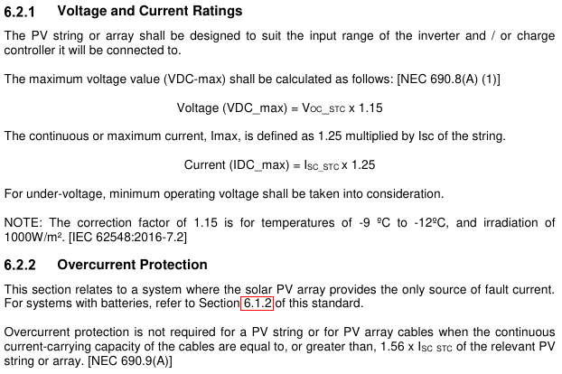
I was wondering where that 125% comes from, because the figure I have is ~160%, then I found them both:
image

So it seems that with 4mm² cable, he would not require fuses to be compliant (I think, there might be a caveat in the next section).

I believe fusing a single string on suitable cabling is not required by regulation and is only required for three strings in parallel or more. In that instance, parallel strings can supply current, which doesn’t apply here. As the inverter is the only source powerful enough to blow fuses.

The 25% (or whatever overrate value) value is a common sense compromise that offers protection while avoiding nuisance failures. I chose 32A for 30A-rated cabling because the PV current will be much smaller and will be unlikely to cause nuisance fuse failures whilst offering a faster isolation time than a higher-rated fuse. You could choose even smaller but eventually, it will be in the nuisance territory.

1 Like

So essentially, from what all of us have said, you want to be in the 20A-30A range, so your chosen 25A is bang in the middle and just fine :slight_smile:

You are probably right. That will work.
I tend to err on the side of avoiding nuisance trips like the plague because I am used to a production environment, and these result in lengthy downtimes.
(Precisely, because there is nothing actually wrong, to explain the plant behaviour).
I am the guy that has to find the reason the fuse blew, and finding a needle in a haystack is difficult enough. It’s just rude when there isn’t even a needle there.

Just out of interest, why do you want headroom on the mppt.
As others have said. Voltage is the key point and sunsynk mppt can handle up to 500v. You don’t need headroom on the current limit and it will just derate if you exceed it but this is also a waste.

Remember you also need to factor in temperature based on where you live. Look at the specs.

I have a 2x 5kw Sunsynk’s and on one I have 6480w and the other I have 6560w. At midday in summer, the max the inverter gets to is 5500w.

On the last string i added, I have 8x jinko 460w. The Voc is 52V and in the early morning, my voltage on this string hits 410V. That at around 10 degrees. Under full load, voltage is closer to Vmp. I’m thinking of adding one more panel to this string and have been monitoring this closely.

When you add panels, try to fill up a string at one go as you will most probably never be able to find those panels new in 6 months.

1 Like

Thanks guys.

This was insanely helpful.

I quote plonkster from a couple of years ago when i built my first system in some random thread, build with absolute safety in mind, SANS will follow.

I have also seen other “quality” installations with CoC’s that is shocking, excuse the pun.

My original installer from years ago, with CoC, screwed up so badly and I only discovered it years later.

We had an existing house in the middle, to the left of the house we built a garage where the solar equipment went, and built another house to the right.

He was supposed to run at least a 6mm to both houses, instead he ran a 6mm to the one, but instead of running 6mm from the same point, he jumpered 2.5mm from the middle house…

So my cottage entire load, was supplied with 2.5mm, which is 3 bedrooms, full kitchen, and at a 24,000btu inverter aircon… what could POSSIBLY go wrong.

My existing panels are mounted to the roof with welded together L channels, fasteners are rusting off, and i only discovered this when i climbed up to install mechanical ventilation as the garage was running hot

Overkill for safety is always my first design principle…

Lastly sorry Vassen,

Reason for the tiny bit of headroom is just on the assumption, just because a car can rev 7k that does not mean it must live there, if it is a tiny bit under specced, im assuming inverter will run a tiny bit cooler ?

I hear you on the panels as well

Designing in a bit of optimal MPPT clipping can result in a net power gain over a year.
In other words, a lot more can be made overall by being prepared to lose a little bit at noon in the height of Summer.
This should explain the point.

1 Like