A while ago I build a Energy logger that was running on a Rpi Zero and should be some where here on the form.
One disadvantage was that the PZero is a bit light and takes almost 5 min to start up and you also need a separate USB psu to run the thing.
It was time for v2.0
Needs :
Device must be able to connect to the internet and have a “setup” interface
Fast startup with some sort of feedback
Log the data to a SD card for “Offline” logging
As small as possible footprint.
As cost effective as possible
After some time playing and fiddling I ended up with 3 models .
Single phase monitor
Three Phase monitor
Single Plug Monitor
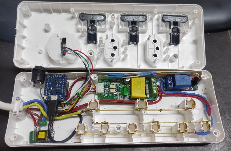
They are all based on the ESP8266 wifi board with a Real Time Clock / SD Card shield for data logging and MQTT for send ding the data directly to my Server. I have a remote MQTT running on a virtual server so that makes things a bit easier.
List of materials:
PZEM004 - 100a Ct and PZEM004 - 10a shunt for the multiplug
Wemos D1 Mini - for the 3 phase meter you need two of them
SD card / RTC Shield for the Wemos
Small 5v PSU that you can intergrade
There went quite some time in the progrming of the ESP to make it as universal as possible and this is what I came up with.
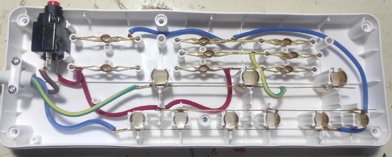
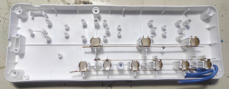
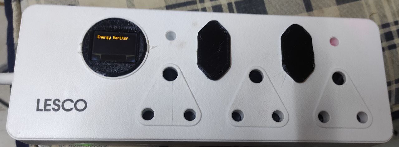
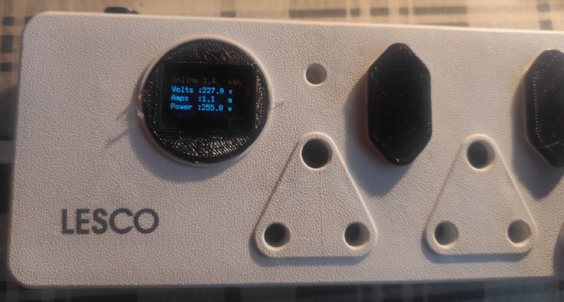
The multiplug Energy Monitor - Only transmit the data via MQTT ( I didnt want the hassle of opening the device to have access to the SD card and battery and also space was a bit of a problem but you have a OLED that displays the data and while I was at it I also added a relay that you can setup for remote control or current control.
I used a Lesco Multiplug ( Think I got it from Builders M) as it had quite some space
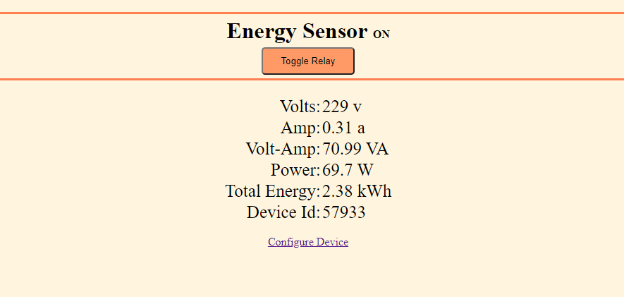
You can setup the Wifi Connection , set a limit to the current draw - should it be too high it will switch off and keep track of the running kwh meter.
It will also send the data to the MQTT server where I then log it as I need to. Personally I prefer Influx Db with Grafana for data logging.
All and all it works well and is use full it you quickly want to have a look at the consumption of a device.
No , I used a Library - IotWebConf.
When the device starts up you have 30 seconds to connect to the AP of the esp and then setup the wifi or if it times out you just push the button again to restart the AP.
Nice project! I do love the OLED display … I need to get some of those going in my own setup
Only concern I have with automatic AP are that it makes you a little bit more open for hacking - if someone could ever figure out a way to power cycle the device it gives them a good opportunity to connect to the AP and take control over the device.
Probably less of a concern with a multi-plug which is probably going to be used for less important aspects and inside your house. But I saw the flaw in a Sonoff SV with Tasmota (which everybody in every forum uses for their gate motors – default has the Wifi AP mode enabled which creates an AP for 5 mins at startup). If I install this in a gate motor and its off during load-shedding, only to come back online and create a 5 min AP, that’s the ideal time to take control of the device and open the gate soon afterwards.
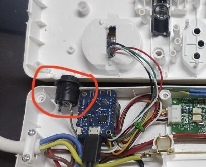
It is a multi control button.
Short press - cycle the Oled between Current values , Max Values and Device status ( Ip Address extr.)
Long Press (+2 s) Toggles the relay
Loooong Press (+15s) resets the device to default
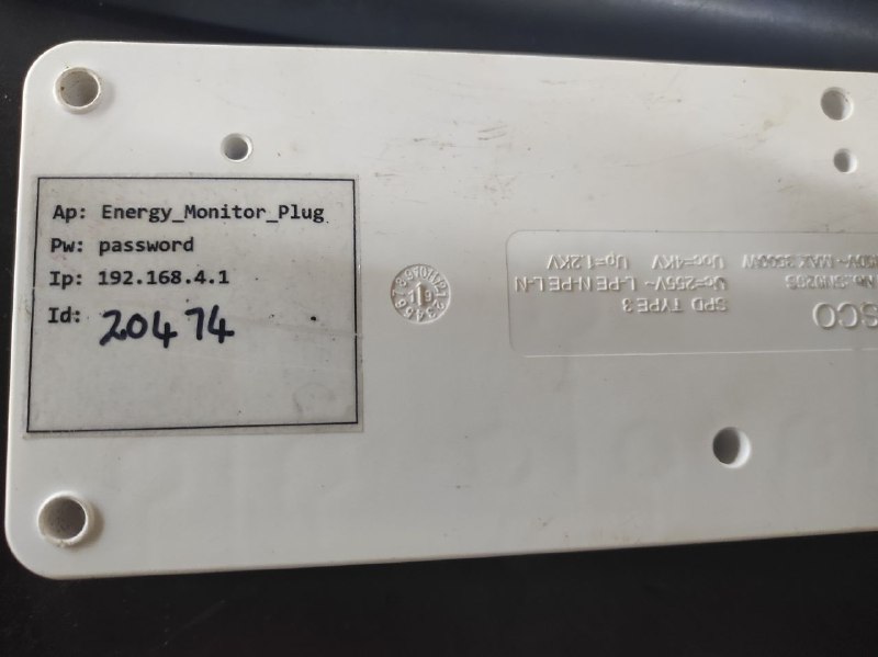
The ap mode is password protected so if you forget the Ap Wifi Password you can reset the device to default. Also the settings menu is password protected so if someone opens the Local address they will see the data but can not alter the settings.
Then if the device times out on the Ap mode and have not connected to the network it will switch off all the online functions and only display the data on the Oled. A short press will activate Ap mode so that you can configure the device.
Last thing was just to place a Sticker at the back should I forget the default pass word ( You also need to change that on startup)
There was , at one stage , even a worse flaw. If you connected the Relay pin to wrong IO pin and the board restarts it will trigger the relay and open the gate…
Tasmota has a WDT so if something is not working as it shoud it will reset the board to clear things up. So it could happen randomly as well.
I do have a tasmota running by the gate but it is only used to report the gate status and switch on the gate light.
Remote only can open the gate. I am not that comfortable to have access control connected to the Network…
just curious… alternate ways to do this.
Install a Sonoff DualR3 into the plug where you’d be plugging this into, it gives you all of this information already, with MQTT output once you’ve refreshed with Tasmoto,
G
True , one thig that I have not been able to figure on Tasmota it how to display data on a Oled.
Oh and in my case I had the PZT models on hand (ordered the wrong type) so might as well use them…