I don’t know if anybody is actually following this thread as my BMS thoughts meander, or if I am randomly broadcasting 0’s and 1’s just like other people whistle to themselves.
Anyway, I came across another little tidbit.
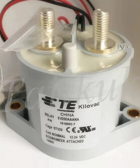
These are the solenoids that are used on that 200A BMS:
Notice: that “Economizer attached” on the label.
It’s a 1990’s invention by a senior R&D electrical engineer at Kilovac called Gilbert Stephen Perreira.
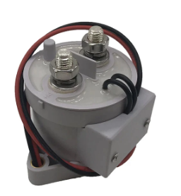
It’s in this rectangular enclosure at the back of this relay:
One of the downsides of using a solenoid is that it needs a strong spring to pull the contacts apart when it is de-energised. So it consequently has to draw a fair amount of current to initial move its armature to click in.
The way they used to be:
Because it’s a permanently energized device, that translates into a relatively high power idle draw, which is the last thing we solar guys want.
It also translates into heat and over time can contribute to the coil burning out.
Earlier in this thread, I pointed out this downside, thankfully I was wrong and things have moved on.
The way they (some) are now.
Enter, the “economizer”.
In a nutshell, far less power is needed to hold the solenoid closed than is needed to initially close it. This new box of tricks allows the initial current surge needed for closing and then consumes just 1.7 watts per 12V to keep it closed. It doesn’t draw nearly as much idle power and doesn’t heat up.
Caveat: I have no idea if you buy these from China if they are fakes or if they actually work.
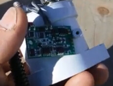
There should be something like this in that enclosure:
It appears I have also fallen foul of the RS485 chip shortage as well, I can get the solenoid 200A BMS with RS485, but the 3 output smaller BMS is only available with UART.
@Louisvdw, I am still a bit hazy on the interaction of multiple BMS’s within VRM, especially when a BMV is in the mix.
If I understand what I think you have told me so far:
1.VRM will combine the data from multiple BMS and represent it as 1.
Showing combined currents, the highest and the lowest cell voltage in the entire bank and the combined state of charge?
2.So if I had a BMS per battery string, it could make a decision to open its own solenoid and disconnect that string and VRM would automatically know to adjust itself to a new battery capacity?
This seems a bit too clever just to work straight off.
If you go and look at the last picture on the Github page for my driver you will see that I do much of this there already in the Charge current control management (CCCM).
With CCCM the driver will limit the charge and discharge currents according to the SOC. We will use the same for the battery modules.
Lets look at an example for the discharge current.
The driver links to module 1 and it states it can do up to 60A discharge. The available discharge current on the GX is now 60A.
Module 2 come online and states it can do up to 40A. The available discharge current is now 100A (60+40).
Module 2 becomes depleted and the BMS raise the flag to stop discharging. The discharge current on the GX now only has 60A.
The inverter will only try to draw current up to what the GX states is available.
There are 2 unknows that I need to test to see how that will work.
I expect that if we want to draw 60A it will try and do that evenly aver both modules which means 30A+30A instead of 60A+0A. Or the BMS could be smart enough to handle this.
In the event of 1) the BMS will open it’s FET to stop discharging when either the battery low voltage or cell low voltage is reached and it will close it again after the alarm conditions are cleared. So you could end up with the FET open/close every few seconds until both batteries are depleted. This will mostly be an issue if the banks are of different sizes and it might be an issue.
This is altogether far more intelligent than I gave it credit.
I can understand how these could be unknowns.
The way I see it, a BMS is a protection device, not a control device.
A BMS cannot manage current, it is either on or off, so it can’t apportion current to a particular string. On the other hand, I think this will be the inherent response of two battery strings in parallel. The most charged string does the heavy lifting until they are in equilibrium.
It will be the load that will decide what gets drawn from the battery. Indeed, even without load one string will discharge to charge up another string until they are at an equal state of charge.
The BMS will only respond to its own string’s current overload condition.
It can though pass on information about the rate of charging and apparently available battery capacity.
The overall voltage across all strings will be equal as the parallel strings terminate on the same busbar. It does monitor voltage on the battery side of the solenoid, but this only yields a different voltage when the solenoid is open.
So assuming each BMS has the same overall high and low voltage cutoff settings ( why wouldn’t they?), they may all make decisions individually, but they will also act altogether more or less.
Maybe though if the most discharged string is isolated first the busbar voltage may recover slightly… But that same individual BMS wouldn’t know to open its solenoid first. It wouldn’t know it was the most discharged string, not from overall voltage anyway.
And as I surmise from 1, they shouldn’t really be in a vastly different SOC in the first place.
So I don’t see these two issues actually being issues, regardless of BMS behaviour.
Where I do see it coming into play is when one string is isolated by something like its own temperature protection or perhaps a single cell overvoltage. In that case, VRM should be made aware that the available power has now been limited, and realize it has to calculate SOC, for a smaller capacity.
(Although, it does still seem that the load cut-off is a voltage threshold in VeConfig, not a SOC one).
It should drop its maximum charging rate accordingly as well.
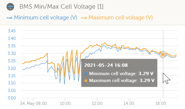
One more, matter if I may, you said previously that VRM only had an interest in the min/max cell voltages. Is this pure for a user’s visual purposes or does it use these values to control charging or switching loads?
The reason I ask is that I don’t see cell voltage thresholds or unbalance delta settings in VeConfig.
Yes and no … Louis drops the max discharge current the BMS can give when the SOC gets low. EDIT: I commented that out … Cronjob does my “throttling” of the inverter.
I can see how VRM can instruct chargers how much current to deliver, but I cannot see how the inverter can be told anything else other than to switch off one of its outputs in an off-grid situation.
Unless you are specifically talking about a grid-tied situation, and saying that it can curtail its power assist function and pass more of the load onto the grid, is that it?
I did not find anyplace where the min/max cell voltage is used as a decision, so that would be only for display. The alarm would pop up in VRM, and then you can use the min/max cell to see which cell/module the issue is. So fault finding display. Also that graph for the min/max cell voltage is a good indication on the health of your battery.
Hmm. That is a good question, but one that I cannot answer.
The driver just limits the settings for what is available. Victron’s system then handles it from there. In an off-grid situation my guess would be that this is the same as when the battery run flat. What does the inverter do then? It will shut down I think. There should be good documentation on this on the Victron website.
@plonkster might also have more information on how this work.
@Louisvdw, Not that I know jack about coding.
But, I found your hard-coded values in the battery.py file, you must have moved them, because your blurb refers to them being in the file etc/dbus-serialbattery/dbus-serialbattery.py file.
You have a “to do” comment beside them, that you intend to have them update dynamically.
I assume that means extracting these values from the app settings.
I would just like to comment that I like this ability to edit the hard-coded values.
This allows VRM to do something in advance of the BMS taking the drastic action of tripping a solenoid and taking the batteries out of the circuit.
I am assuming that if the dynamic values are used then VRM control and the BMS trip will happen together. This won’t give VRM a chance to fix things and possibly avoid the trip.
I would like you to keep this option open somehow, even if you master the dynamic update.
Or at least, have the VRM setting be at a relative margin to the BMS protection trip setting.
By the way, thank you very much, between yourself and @Plonkster this forum is a blessing to Victron users.
Correct. So what ever you set in the BMS using the bluetooth app, the driver will pick up. But in the latest VesunOS versions you can also set a limit under the DVCC settings. The lower of the 2 settings will be used.
Yes I did though of using a margin.
Yes they have been moved, but the latest release (v0.3) still have them in the old location that is documented. You must have downloaded the latest code or an beta version and that have the new file structures is.
It’s for diagnostics. When someone complains that a battery raises an overvoltage alarm, it helps to know why, and it also helps to give an indication of how bad the imbalance is (difference between highest and lowest cell). An experienced installer can use that to override the charge voltage. So basically it helps everyone, informer users, installers, and the poor suckers who have to support them
@TheTerribleTriplet , I have seen this video, but you’ll have to refresh me about what I asked. Not that I will have forgotten it’s just that I have asked so many questions on this thread.
I am still not sure which question, but I don’t have any real outstanding doubts about this solenoid, only if the economiser aspect of it actually works.
These are actually quite expensive solenoids when bought from reputable outlets. More expensive than I can source the entire BMS in China.
So I wonder if they are counterfeit and if so do they match the original’s performance?
Other than that I am good with this BMS.
Yes Alibaba is meant to be a wholesale type of business dealing from business to business. AliExpress is more a retail type of business dealing with the public. We can get into Alibaba because they do samples and they can’t pass up a sale.
I got my batteries through Alibaba as that was the best price.