Got some pressure sensors on the way from Aliexpress.
1 x 10Bar - Water pressure after booster pump.
2 x .5 Bar - Water pressure at the bottom of tank in pipe to booster pump, got 2 tanks.
1 x drop in 5M transducer/sensor - Will be configured for a friend, he has a cement tank that has a drop in pump, so will add a drop in sensor lying at the bottom.
All are 5v output based.
I’m looking for a sketch’s that can measure the voltage, convert to water level after having been zero’d, but then send the data to MQTT broker.
If you would like to go Wifi , you will need to setup a voltage divider to get your volts down to maximum 3v (Personally if would say 2.5v just to be safe).
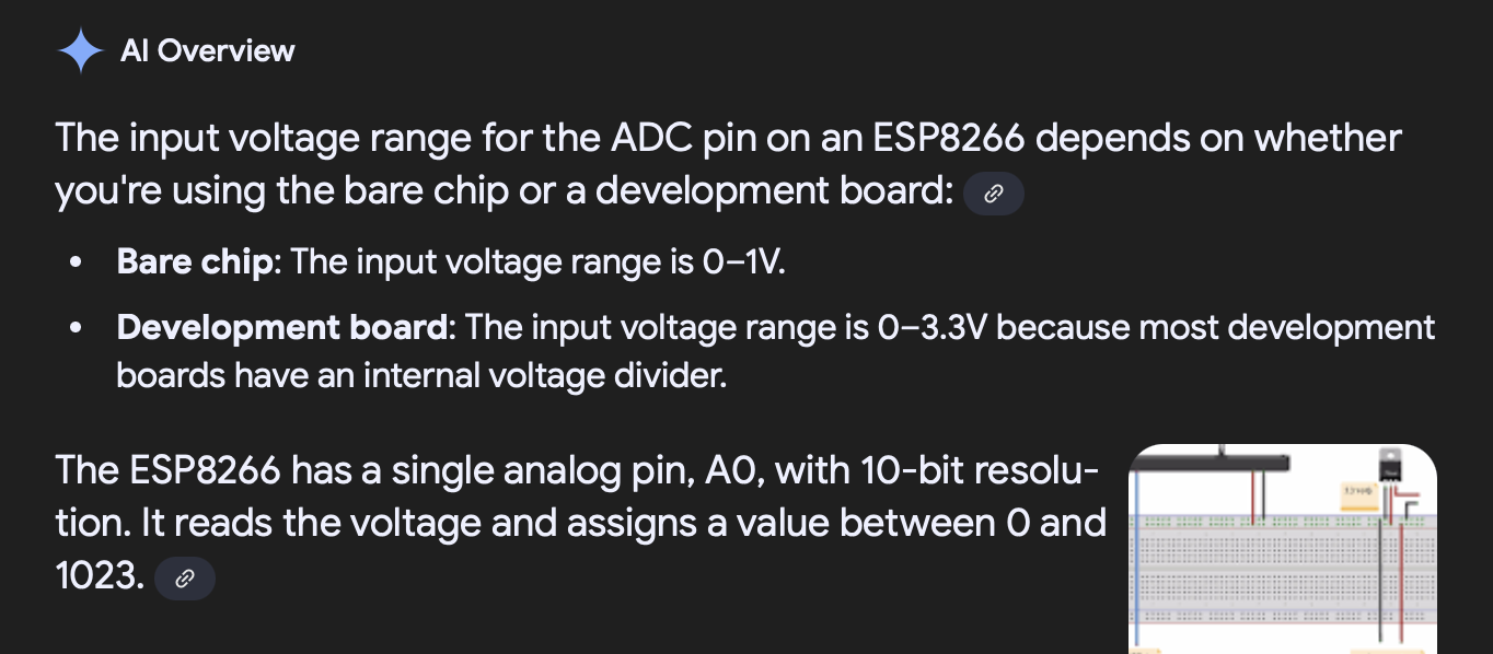
The ESP chip analog only reads to up 3.3v there after you get magic smoke…
Here is a very good tutorial on ADC read for ESP32 - ESP32 Analog Input with Arduino IDE | Random Nerd Tutorials.
Once you managed to read the ADC value you can map it to your pressure that corresponds to the pressure at that voltage.
After that part sorted you can then move over in publishing the data to MQTT
Here is a very good tutorial on how to read and publish sensor data via MQTT ESP32 MQTT Publish Subscribe with Arduino IDE | Random Nerd Tutorials
The example should get you going fairly quickly.
Few things to consider
ESP board only have one ADC , it you want to read all the sensors on one board you will need to get a ADS1115 that can read up to 4 analog values.
How are you going to power the board (Things get messy very quickly with all the wires going all over the place).
Hope it helps
just spoke to supplier… they can ship 5v input and a 3.3v output model, requested they change my order as such.
allows me to power it from the 5v power pin, but 3.3v for the ADC.
no magic smoke
G
I use a few esp and nodemcu boards and send data to HA, flash them with ESPhome, have 3 running voltage dividers(on the nodemcu’s their adc pins is a lot more stable than the ESP(older ones))
Mind sharing the links for the pressure sensors you ordered?
ESPhome have a lot of examples so its fairly easy to get things running, they also have things to filter out your readings, especially if you measure from above in a tank and have water coming ect.
Getting the code going should not be to difficult and quite happy to help but I suspect getting the hardware setup for the programming is going to be the fun part.
I had a look at the sensor on Ally and it seems like the input PSU is 24V DC.
So just thinking about it you will need
24v PSU
Buck converter to power the ESP chip
ADC converter for the sensor inputs (ADS1115 ADC)
PCB to put them all together
I would say a test rig to run your tests, water don’t mix well with electronics
The programming itself is fairly easy, you could even program the D1 with Tasmota and ADS1115 I2C Devices - Tasmota
It will then transmit the Analog values via MQTT and you can convert them post process in Node Red , Phyton extra.
Looks like i got 1 x ESP32 based NodeMCU, believe they have 4 analog ports which will work for me and multiple 8266’s, and for them i only need 1 analog port for 1 sensor.
options is as you said to use / abuse tasmota… and might do the 1 D1Mini with the 1 sensor using tasmota… as thats going to a friend and it’s more hands off… for the NodeMCU with the ESP32 that will go here with me… might be keen to try a custom Arduino sketch for that, where we measure the 3 levels (might be a 4th down the line) and then send data to a MQTT… if there is problems with these can always then redo as Tasmota… now to jsut wait for the sensors… can then check confirm things…
need to put a water tube together that i can mark out to be able to zero/calibrate the setup…
G
As far a as I remember the 8266 have a ADC input range of 0-1V just make sure to divide the voltage enough. Have a look at RandomNerd’s site if you haven’t already. There is a ton of valuable info. He’s site is usually my first stop when I do anything with ESPs.
I have not used the ESP32 yet. For the 8266 D1 Mini type boards the 0-1v applies. You might need to add a multiplier somewhere in your calculations. I use a multiplier of 3.3 to get my measurement correct. I have not tried a Dev board. I would treat the board as 0-1v and see what voltage is measured before decreasing the divider resistance to increase the resolution.
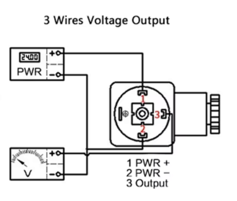
Need someone to check my understanding… please see attached picture.
My units are 5V input, 0-3.3V output.
1 → 5v
2 → N - common
3 → Analog # (3.3v) MPC3008
The MCP3008 happily can be powered by 5v. so plan is to run that as a common positive in, to the chip and the sensor.
Then common negative
and then just the sensor output onto analog 0 in for the first sensor, and 1 for 2nd and so on.