I think I have these features already…
What I’m wanting is an equalising capacity to stop one cell getting out of step with the others and shutting the battery pack down.
I am no expert so I would like to hear if anyone can comment on how important this is. (I have seen cells maintain their voltage and are always out of alignment through charge/discharge cycles with the others despite them being identical…??)
From personal experiences I can tell you it is extremely important to NOT have cells shoot out… ever.
Can also say that in such a case, not passive nor active balancing will help much, if at all.
Top balancing the bank and sticking to like 3.45v per cell, dropping charge at high SOC, not chasing 100% SOC, goes a long way to steer clear of that drama.
Keeping the bank in the flat of the curve is a good practice, as some has mentioned, me trying that.
And when cells do shoot out, first prize is to top balance the bank again, 2nd price is to manually intervene by dropping the charge amps at higher SOC to give BMS time to balance. But this requires hands on as the cell/s shoot out in seconds at times, and it is tedious, even with a bulb or 6 to help.
Stripping the bank and top balancing it in parallel is much faster.
1 Like
What size cells are you referring to?
Precisely the kind of thing I had in mind. In fact I was thinking of the 3305, which is a lead-acid balancer that uses an auxiliary cell.
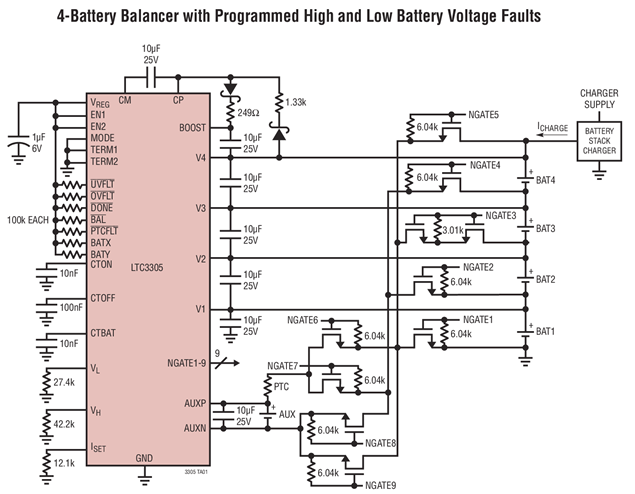
The idea I had in mind would be similar, except it would connect the high cell to a low cell via an isolated DC/DC converter. The 3300 appears to do something like that, except it uses multiple transformers, and by switching the right pair it can transfer charge between any two cells.
But as you say, quite a bit more expensive.
For DIY people. Must ask as it has been mentioned a few times to date… what is expensive for a BMS with the right ‘parts’ ?
10% = of cell value?
Will it keep the cells under control for 3/5/10/20 years and interface with the system?
BMS’es today have a function, assuming certain circumstances. Exceed those, more parts required.
Like some say you need active balancing the first week or two, then it is wasted. I don’t agree nor disagree. No one has run a lifepo4 bank for 10+ years… Methinks we all are still learning?
If a BMS is like 10% of cell value and it can extend the life of the cells, guaranteed, no intervening, I’ll buy it.
1 Like
Lifepo4… the smaller 3.7v cells more intricate to ‘control’, methinks, due to amps, not volts per se, due to their size and therefor their tolerances for drama’s.
Back in the day, the ESKOM protection budget norm was 5 %
In other words, it was worth spending 5% on protection assets to protect 100% of the vulnerable primary plant.
It was adequate then…present day…I have no clue.
1 Like
I’ve read that LiPo batteries have fallen out of favour due to their high energy density.
So they need to be protected from going up in flames and managing each cell is mandatory.
The popular way of achieving this (as per power banks etc.) is to pack them in parallel and then use a boost converter to crank the voltage up to the required level.
My suspicion is there’s an efficiency cost in doing this (as there is with a regular 220V inverter)
That calculation does not scale well to smaller plants. Say you have 20000 cells, and you 3% to fail, having a budget of 5% is more than adequate. If you have 20 cells, the math actually becomes more complicated, because now you cannot hide behind the large numbers anymore.
Of course that also does not translate directly to BMS costing. One thing I can add - the big name batteries don’t have active BMSs - they have simple top balancing resistive balancers. What some of them do have that can prolong battery life is algorithms that instruct the inverter to lower charge or discharge current based on SoC, temperature and internal resistance. I don’t think that is realistic for most DIY batteries…
1 Like
I believe the LTC3300 boosts from cell to pack voltage, discharging a high cell to the pack, thereby redistributing charge. So you don’t have to connect a high cell to a low cell, just a high cell to the battery terminals (through a boost converter). You can do this with a single transformer with multiple primaries (one per cell). If you had to be able to multiplex each cell to any other cell, you would need a matrix of switching devices that can handle any offset.
In the case of switched cap active balancers, you can only move charge to the adjacent cell (through a cap) so you have to repeat the process until you have moved charge from a high cell, through other cells to the low cell. (In practice it does not happen exactly like that, but that is the bigger idea).
Anyway, I am sure you knew much of what I wrote, I just wanted to paint a better picture for anybody else that reads this.
1 Like
I didn’t look into it that deeply… I should have ![]() Boosting to a single place is certainly simpler. And simple/boring is GOOD in electronics. Ask any BMW owner.
Boosting to a single place is certainly simpler. And simple/boring is GOOD in electronics. Ask any BMW owner.
Edit: I note that for larger batteries (over 12 cells), it cannot transfer the charge all the way to the top, so you kick the can 6 cells up (an imbalance in the first 6 cells goes to cell 12, an imbalance in cells 7-12 goes to cell 18, etc. IE it turns it into little sub-packs. And you can daisy-chain this thing and go up to 1000V… nice…
1 Like

2 Likes
Like this?: https://www.robotics.org.za/CHR-4C?search=18650
That’s fine. It will only do balancing, though. And most of them only balance at top, so they do nothing until the first cell reaches 4.2V, which is fine, unless you want to charge the cells to 4.0V to prolong their life…
I’m aware of lead acid stats in this regard but have no idea with LiPo…
Does anyone have this info??
Saw this video and thought of this question, maybe it sheds some more light?
Active balancer test failure. Trying to show how balancers work. ![]() - YouTube
- YouTube
This comment from Andy, about 30mA like balancing on large ah cells, not the first time he has made the comment, is stuck with me …I have seen the exact same.
Your bank goes out of balance, very little bar top balancing will help. i.e. take all the cells out of series, connect them in parallel, and top balancing them, is the only real thing left to do.

In the end, you have to take charge from the high cell, put it somewhere, and then release it either into the battery as a whole (which is what the LTC3300 does), or into a low cell.
The “putting it somewhere” part is where balancers differ. A passive balancer dissipates the energy into heat using a small resistor. Active balancers store the charge either in a capacitor, or in an inductor (as magnetic energy).
With an inductor, the magnetic flux cannot be stored for very long, and if you saturate the core it becomes inefficient. So what you will usually do is push some current through the coil (causing it to store a magnetic flux), and then you will very quickly turn off the one switch and turn on another to let the coil discharge into something else.
Now Lenz’s law says that the inductor kicks out a reverse EMF if you interrupt/change the current flow, so that’s what is used here. That reverse EMF can be caught and pushed into another cell, or into the battery as a whole.
But… you soon realise that using an inductor to transfer regulated amounts of charge is essentially the same thing as a switch mode power supply. So inductive active balancers are essentially isolated DC/DC converters sucking energy from high cells and moving it elsewhere 
I had a friend who worked for Eskom back then and I recall him saying that another budget norm was the optimal transmission line was planned for a loss of 10%.
PS: Phil, have you returned to SA with your 8 suitcases??
I did, but it was 4 x 32kg suitcases. I’ve got to do the same thing several times in the next 12- 18 months.
(Transmission losses and the protection budget are two different things).