Jip, I concur. Mine is outside in the weather, the Shelly temp sensor on top at the outlet.
Overnight is not an issue.
Jip, I concur. Mine is outside in the weather, the Shelly temp sensor on top at the outlet.
Overnight is not an issue.
@Phil.g00 I’ve been thinking a lot about this comment of yours and I’ve resurrected this topic to take issue with what you claim.
My understanding is that it’s the PV panels that vary wrt their power generation characteristics that requires the use of a MPPT to extract maximum available power.
The Geyserwise Dual incorporates a MPPT to do exactly this. I’m sure this isn’t a nice-to-have.
I have one of these so I’m available to experiment if required…
I am always willing to explore the integrity of my beliefs.
This is the context of my statement.
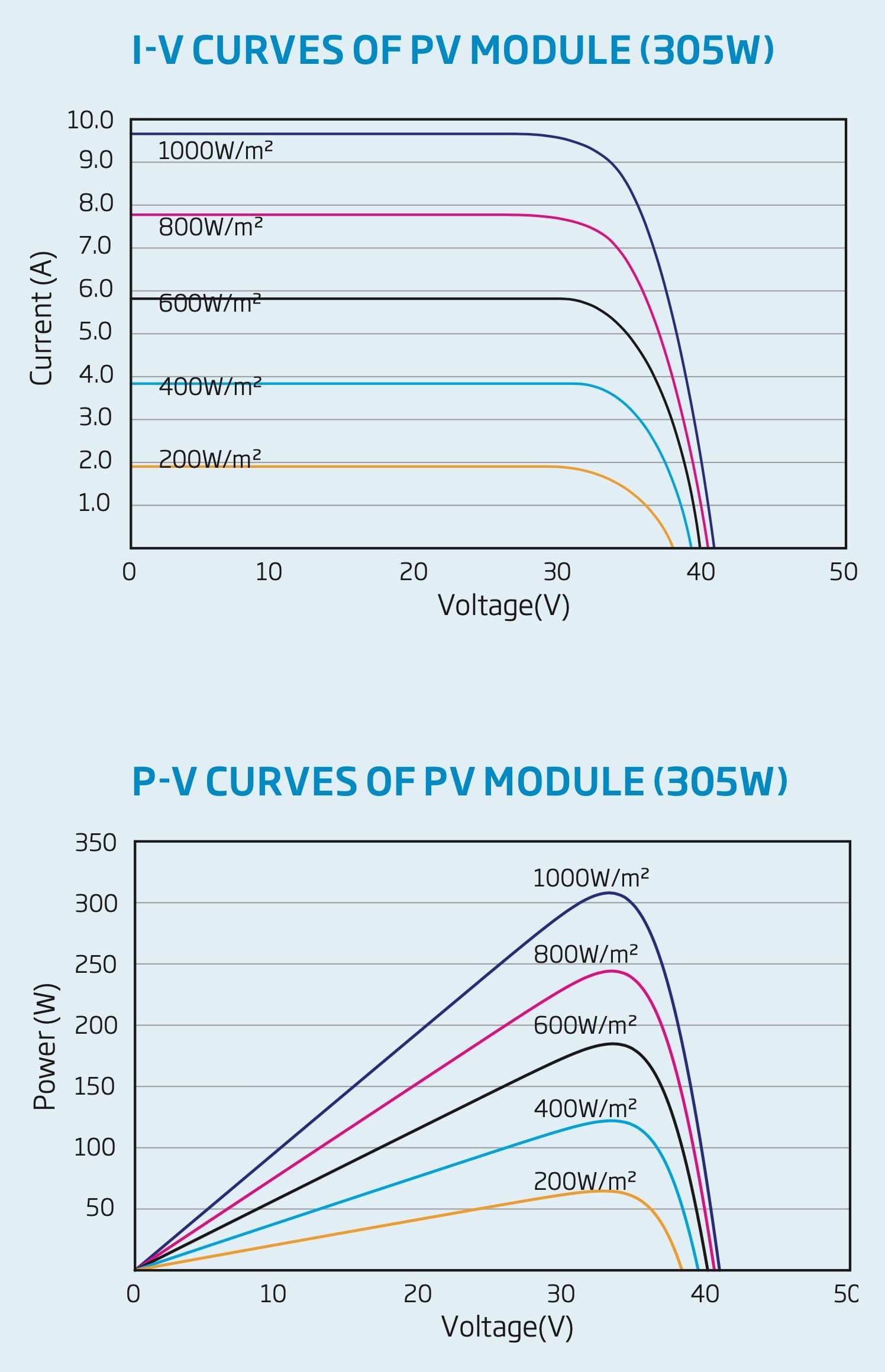
A PV panel is a voltage source whose output voltage remains constant and doesn’t vary with the amount of current drawn in the circuit.
This is as evidenced by these all-to-familiar curves I robbed of the WWW.
OK, so let us do a rough test of my theory. Against the values R, R/2 & 2R below. ( For discussion purposes, I am going to portray the PV panel as an ideal voltage source, which it only approximates).
At R, I achieve VMpp and Impp, and no more current is available. And the equation P = I^2.R =X watts
At R/2, I achieve VMpp and Impp and no more current is available as well, but now the equation P=I^2.R/2 =X/2 watts. (In reality, not being an ideal voltage source, the voltage will start to collapse, and the current will tend towards Isc, but the effect is still the same, i.e less power).
At 2R I achieve Vmpp but Impp/2 because I can’t exceed the constant voltage source. The power equation is P=(I/2)^2 x 2R, also equating to less power than X watts.
Being a voltage source, the current output of the panels will vary as the available sunshine varies, but the voltage and the element resistance are largely constants, and the power relationships for different values of R will remain.
If I understand your statement, you say that an MPPT will allow the panel to create more power by operating on a different part of the power curve.
So, I’ll give you an opportunity to present your case.
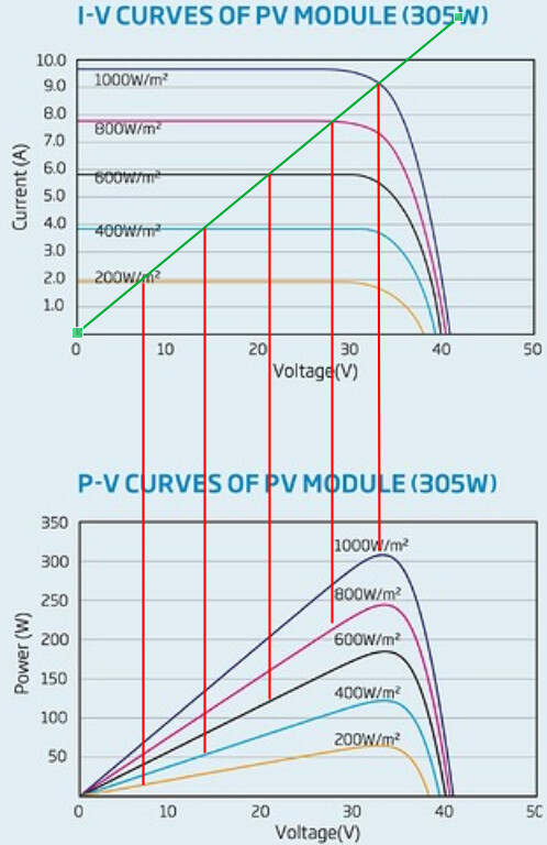
There is a simple tool you should learn in standard 8 maths - solving simultaneous equations by graphing:
I have added the graph for R in green to the plot. Where it crosses the other curves is the solution to the simultaneous equation for that light level.
Project those points down (red lines) to get power at that operating point.
Compare that to the peak power to see how efficient you are compared to an MPPT.
Please follow through with your interpretation for demonstration purposes.
Not sure how much further you want to take it. Those are direct solutions to the device equations.
If you look at the 200W/m² graph, power produced into a fixed resistor is around 15W vs 60W at MPP. Only getting 25% of the available power.
For those not familiar with this analysis technique…
The green line is the I-V curve for a resistor of value ‘R’ chosen so that it R = Vmp/Imp.
At any point along the green line, I=V/R (characteristic curve of a resistor).
The other lines are the characteristic curves of the panel as determined by the manufacturer.
Seeing as the resistor is connected directly to the panel, the panel voltage must be the resistor voltage, and the panel current must be the resistor current.
So only points which are on both curves (that is, where they cross) can be valid solutions to both device equations at the same time.
It is a remarkably simple analysis technique, and gives you a good graphical insight into the system behaviour at the same time.
So after some thought, an MPPT can indeed reflect a different impedance to the PV that allows the PV to operate at Vmpp whilst delivering more current in some of its range.
The selected fixed resistance delivers about 5 % more power than an MPPT at optimum conditions. I guess that things are even about 85% of optimum, and the MPPT will deliver more power in sub-optimum conditions below this. ( An MPPT being about 95% efficient).
That’s the technical evaluation. The less optimal the average conditions, the more viable an MPPT would seem.
So from a technical efficiency aspect, I concede the MPPT has the edge, although I don’t see it as massive. Down at the lower insolation levels, there is greater disparities % -wise, but that doesn’t translate to a whole lot of absolute watts at those low levels
I am glad you pursued this because it gives me insight into what is still left on the table power-wise.
So to my whether my statement was heresy or not?
That isn’t a purely technical evaluation. It boils down to whether the geyserwise gizmo delivers an efficiency better than could be achieved by buying additional panels to the tune of its cost.
Edit: I am going to revise my element calculation, though, to this:
R = Vmpp/ I, where I is the midday current value on a representative sunny day.
That will customize the element to be more in tune with the particular installation.
IIRC over an optimal day, with optimal fixed panel angle, the difference in power between optimal resistor and perfect MPPT is around 30%.
Which is not much if you consider that an extra panel is probably cheaper than a MPPT. The big issue is finding/making a heating element that has the optimal resistance, as the efficiencies fall off very quickly with non-optimal resistance.
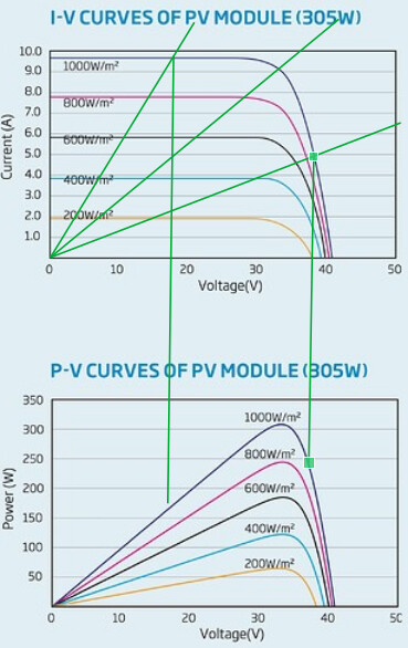
Here is an eyeball of the 2R and R/2 operating points:
R/2 is almost 50% down and 2R about 30% down.
The graphical analysis does show something nice though. Rather err on the larger resistance side, as (1) the efficiency loss is smaller, and (2) you will pass through MPP at some point in the day as light levels fall.
Yes, my revised calculation will weight things to a slightly higher resistance value for the element.
That is not as big an issue as it seems. The clip points to a spreadsheet that translates element resistances for 220Vac and 110vac elements into ohms. These off-the-shelf items are over-spec in terms of voltage and power ratings, but only the element resistance is of interest. there are quite a few options available.
On this topic, our very old 150l geyser recently burst. I replaced it with a new 200l class B. I also repiped so that the new 200l feeds the one bathroom that was serviced by our other old 100l geyser. Having only one geyser, and it being a new one, definitely saved quite a bit on standing losses. Where I used to spend about 9kWh on heating a day, I now only do roughly 6kWh (worst case).
(Rough estimates, don’t have many data points yet and the days I looked at weren’t 100% comparable - I expect in the favour of the old setup)
You sure? The chart seems to suggest that it is a current source (where the current depends on the light level) and the voltage varies depending on the impedance it is matched with.
I am mostly in agreement with you though. If you live in an area that has good year-round sunshine, you can pick a panel/element combination that lands you at the 800W/m^2 peak, and the slight loss on a day with more sunshine would be acceptable because you save the cost and complexity of the MPPT.
For your average 150-liter tank with a 3kW element, that means aiming for 13A and a Voc that’s about 10%-15% above 230V. And I think that’s probably the hard part right now, although we’re beginning to see panels pushing over 10A, for a really long time that’s roughly what you got, a panel with a Vmp in the mid 40s, pushing about 10A, giving an STC power value of mid 400W range.
With a 2kW element, you have a better chance. About 9A is what that element will do at 240V, so 6 x 335W panels would probably put you right where you want to be.
Trouble is, you cannot always find the exact panel you need.
Yes, the model for a PV panel is a current source (with a voltage limit).
Yes, I was wrong, reconsidered things and conceded the point in my later post.
Thanks for this graphical interpretation. It’s great when one can start to get to grips with these technical issues and tie them to their specifications.
I’ve always been aware of the MPPT concept but my grasp of the subject has been wanting.
Thanks again to all for this inspiring discussion!
Evidence of a misspent youth… Had to do all these analyses back in 3rd year when we had to design and build an MPPT using discrete components.
Was interesting, but quite challenging.
Who would have thought that those lessons would finally come in handy 30 years later ![]() .
.
No doubt! I wouldn’t know where to start…
How is the impedance of the input adjusted to achieve this? (I trust that you don’t switch in a fat resistor or two ![]() )
)
It is basically just a switching regulator, where you adjust the duty cycle for maximum power transfer. (The combination of duty cycle and inductor reactance gives you the effective input impedance.)
EDIT: If you were wondering how the duty cycle is adjusted, we used a perturbation algorithm - just regularly adjust the duty cycle up a little and down a little, and if one is better, then keep it and start your next perturbations from that point.
As I recall there are two ways. The one is the “perturb and observe” method. If you see the power go down, go the other way. The effect is that it tends to wiggle about right on the cliff’s edge of the P/V chart.
In reality it is more complex. With shading, it is possible for multiple peaks (local maximae), and you don’t want to get stuck on a local maximum that’s less than the global maximum.
The other method is called Incremental Conductance. This method knows when it has reached a peak, and will then stop the wiggling about. It can also determine the direction it needs to adjust in by looking at the relation between dl/dV (first derivative of the I/V function) and –I/V.
I seem to recall that when dI/DV = -I/V you have a peak, and I’ve seen someone proving the math, but I have no idea where I saw that!
Yeah, there are better algorithms - but I would not want to try implement anything more than a perturbation algorithm with discrete components ![]() (well, OK, we were allowed OpAmps too, so not entirely discrete). In the end, it worked surprisingly well. Never had any issues with it sticking at endpoints.
(well, OK, we were allowed OpAmps too, so not entirely discrete). In the end, it worked surprisingly well. Never had any issues with it sticking at endpoints.