Victron, Fronuis - ESS

Modify the firmware and remove the pylontech quirk. I am sure I explained it elsewhere before, search function should find it.

The best long term solution is obviously that the BMS should stop identifying as a Pylontech battery. If the supplier said it is compatible, he needs to fix that :slight_smile:

What I’ve seen a few times now, is that apparently the Sunsynk/Dye inverters want to see that PN. It doesn’t work without it. But if you leave it in, then a Victron system will detect it as Pylontech. And there is no real way around it, because for backwards compatibility it has to do that.

Edit: Here it is (the short term solution):

1 Like

How about the old three-cats-in-a-trenchcoat switch in the Advanced UI? :man_facepalming:

Thanks for the comments advise gentlemen. I will pass on the the installer and get him to advise. I unfortunately am 10 000 mile away from home so much of the corrospondance is done ove whatsAp and email. Your advise and constructive criticism always welcome.
regards

Help, it appears someone has removed my Fronuis primo data manager card and now I need one. Can any one help with suppling a data manger card for the Fronuis Primo 5.0?

I have been told a company removed them and fitted there version of wifi for there back feed preventer some time ago. So yeah, i got to buy one now at R6000. Not a happy camper.

On another note you were right with the battery and PN, the supplier is adjsuting the software as we speak

Best regards

Andy Alpes

So my Katbatt battery has been successfully connected to the Victron miltiplus, my installer and the battery manufacturer adjustwd the firmware of the BMS and all connected and operating as intended.
Big thank you to KatBatt(luiperdskop) for the excellent support with your product.,

3 Likes

Hello all
When installing multiplus 2 GX with Fronuis primo in AC couple do I require a CT in the AC in from grid or a victon meter? What controller do we use to prevent export?
Regards
Andy

A Victron-compatible meter is required. It is well described in the Victron documentation.

Hello Phil
Thank you for your advice.
Best regards
Andy Alpes

Small extra note (although this is also in the documentation), but it depends where you put the Primo. If it is on the output of the Multiplus, and you have no loads on the input side you want to feed, then you don’t need an extra meter. The power measurement built into the Multiplus can take care of measuring backfeed and limiting the Fronius.

If the PV-inverter is on the input side of the Multiplus, or you have non-backup loads you want to power (very probable, if you are heating water or running pool pumps), then you need a Victron-supported energy meter. Probably a Carlo Gavazzi ET112 (assuming single phase) or a ABB B21 meter, plus the usb-rs485 cable.

The input is on the AC1 output so it is not in parellel but my installer could not get any control yesterday and advised i need a CT or a energy meter.
In the documentation, it says if the GT inverter is in parallel, you need an energy meter but does not mention anything when in it is connected to the AC1 output. My installer is very inexperienced with Victron and fronuis and i believe just too much in a hurry
Regards

So your setup is like this (the PV-inverter is on the output, in the red circle)?

Do you have any loads on the input side (blue circle) that should benefit from the solar energy made by the PV-inverter?

If yes, then you need a Carlo Gavazzi meter (as indicated) wired to your GX device (which is in the Multiplus if I understand correctly, it is a MP2-GX?). And you need to configure the Multi with the ESS assistant and set it all up to work correctly.

The limiter only works if the Multi is set up for ESS.

Yes, there has been some requests for making the limiter also available in other setups. And soon it will happen, as soon as one particular R & D guy moves over to a Multi RS (HF inverter)… which should be around July-ish :slight_smile:

1 Like


This is the configuration, when the GT was connected we received figures of approx -4000watt at the Grid, no apparrent reduction in solar yield and the frequency stayed the same.

Regards
Andy

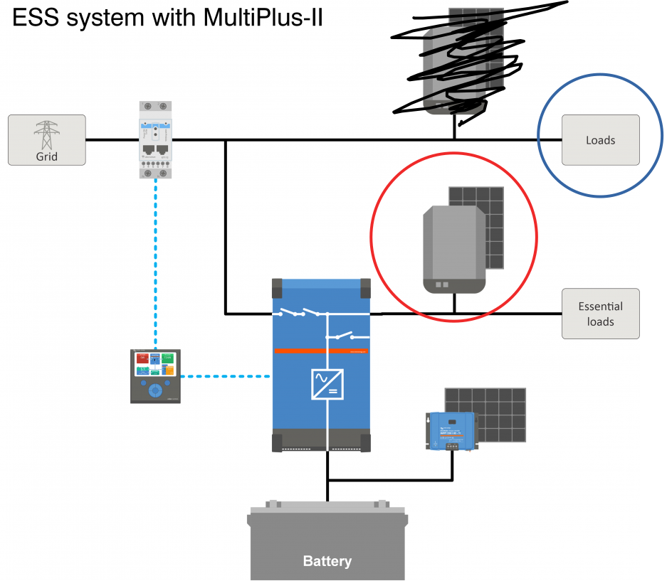
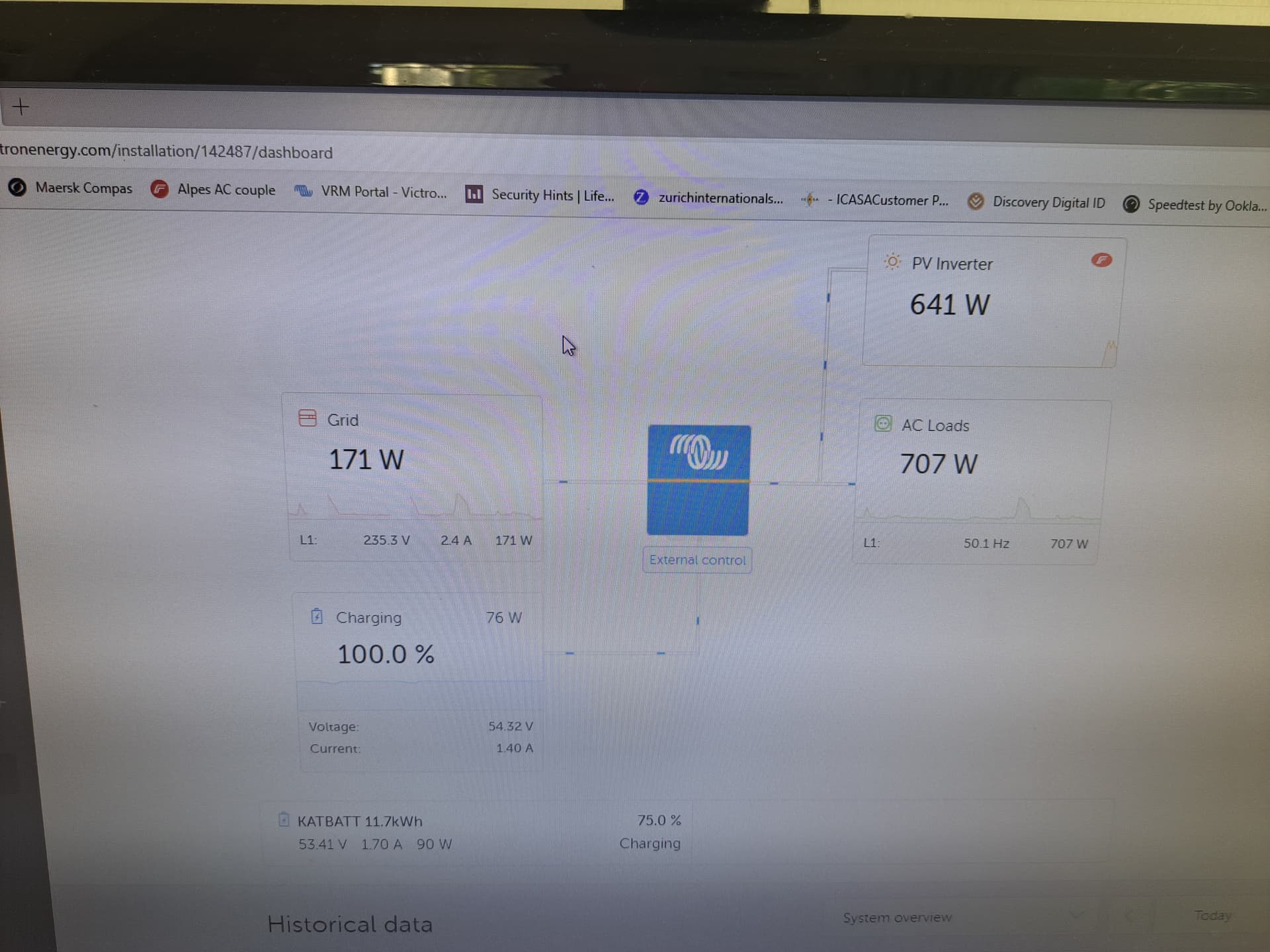
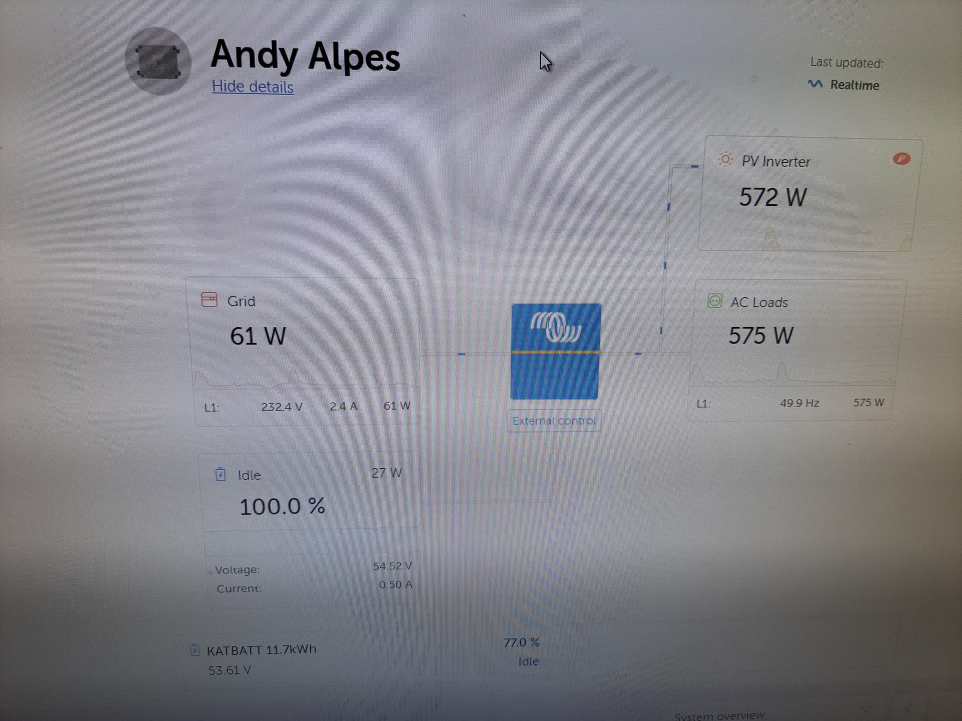
In your first picture I see an SOC of 99.5%, and ESS #1 and #2 shown, which means you have minsoc set to 100%. Don’t do that… rather set “Keep Batteries Charged”. All sorts of weirdness shows up if you do that (but we cannot take it out, at least not without thinking about it a bit, because some people somehow rely on it).

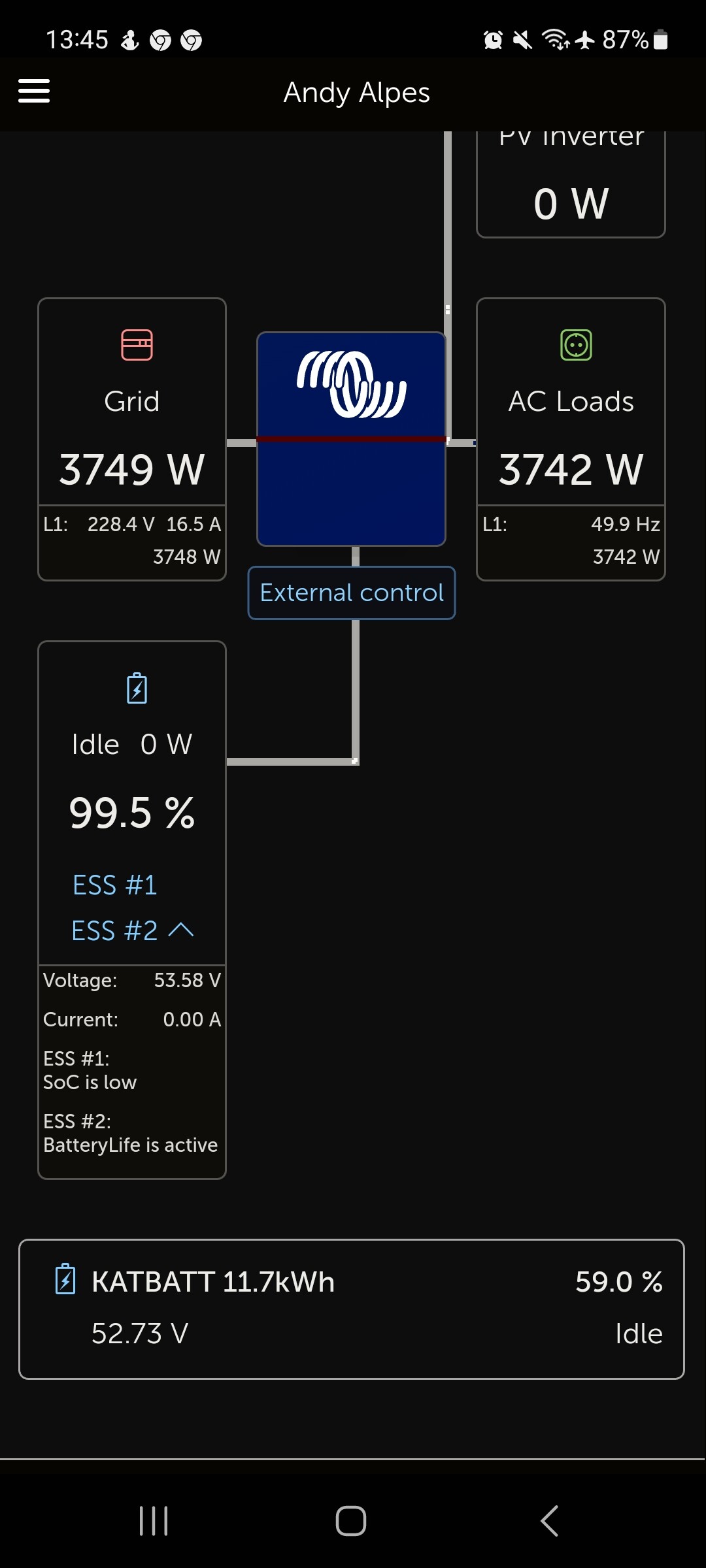
While connected to the grid the frequency will always stay the same. We cannot shift the frequency of the grid (at least, not without making the installation significantly larger!).

Anyway, I know what your problem is. The Fronius is not properly commissioned. It is using SolarAPI instead of sunspec. To change this you will need the service login to the Fronius inverter, then you need to log into the web interface of the Fronius inverter, go to the Modbus tab, and set it to TCP (it is disabled by default). The sunspec model type should be set to INT+SF.

Then go to the DNO Editor, and set modbus to have the highest priority. Optionally (if you want to do the below), set “Dynamic Power Reduction” to have the second-highest priority.

If you want the Fronius to stop generating when it loses contact with the GX device, then you need to configure “Dynamic Power Reduction”. By default it is set to “No limit”, but if you set it to “Entire system” and then set the limit to zero, it will shut down the Fronius if it loses contact with the GX.

How this works is in the priority. You set modbus to have the highest priority, but that has a timeout of 2 minutes. If no comms is received for 2 minutes, it drops to the second item in the list, which shuts it down.

This is in the manual as well, here, in section 4.3.11.

Note that the Fronius web interface has changed over the years, it is not identical for all models, but should be close enough to figure it out.

2 Likes

Wow, thank you for all the invaluable information and advice
I have been scratching my head and had come to the conclusion that the fronius was not configured properly but had no idea what or where to begin. By looking at the Ap I could see the frequency change during loadshedding but there was no control on the PV. The fronuis would eventually shut off on high frequency in the end. During operation with ACin connected it charged the battery but also back back fed the net.
Thanks to you I have now have positive issues to check and adjust.

You also need to set the country code to MG50 (Microgrid 50Hz) before the frequency shifting will work properly. On my mobile right now so can’t tell you how, but it’s documented all over, even some YouTube videos.

I have set the Fronius primo as per your instructions but now ther is a loss of comms between the mulitplus and the fronius.
Possibility because we changed to TCP.
I am unable to access the multi as the installer has pasword and I cannot get hold of him. So it would apear Fronuis shut down due no com with multi possiblily?

So system up and running as intended thanks to Plonkster.
Multi plus 2 GX in series AC couple with no grid feed back.

Morning all, after adjustments yesterday to the Fronuis set up the multi is controling back feed extreamly well.
However a quick question which has been bothering me, Muli indicates battery at 54.52V and BMS indictes battery at 53.58V now wich is correct. I could measure, but is a digital multimeter accurate and fast enough? Secondly I have read that its possible to clalibrate the victro ns CT if necessary . Is


this true?

It is normal for there to be some discrepancy, and I have seen as much as a volt in the past. I’ve seen both BMSes and the Multi being off, so my first check would be to measure it with a good multimeter.

There is a way to recalibrate the Multi, but I’ve only heard of it, and usually the Multi is calibrated in the factory and it is rarely necessary to mess with it. You will have to ask your supplier about this, because this procedure likely needs to be done by someone who knows how.