You can make Vref anything from 0.25V (although linearity gets really bad below ~0.5V) up to the supply voltage of the MCP.
BUT the analog input voltage must not go more than 0.6V above the supply voltage. As long as the sensor is guaranteed to only produce max 3.3V output, then 3.3V is fine for both supply and Vref.
(Personally, I would include a 1k resistor in series on the analog input, just to be safe. And possibly also a schottky clamping diode, to be safer still.)
You can not connect 5V to a RPi GPIO pin. So if you powered the MCP from 5V, then it’s output (which connects to an RPi input) will also be 5V, potentially damaging the Rpi.
So, basically, connect everything (except the sensor itself) to the 3.3V supply pin.
1 Like
Justin.
You not reading, seeing what I’m saying…
We have VCC on the Transducer, thats it’s input voltage, and I’m thinking of powering that of the 5V pin on the RPI.
The transducer design is that it give 0-3.3V output on the data pin, that data pin goes onto the MCP3008 analog input.
My ask is… I power the MCP3008 on 3.3V on VCC and vRef.
The channel 0->7 aka pin 1->8 input pins will only ever get 3.3V because thats what its output is designed as.
The RPI will never see 5V coming back at it, it is connected to the MCP3008 SPI* pins. even the MP3008 can be powered by 5V on vCC and vRef, but I’m not thinking/planning that…
G
but do think by this line you are sorta following my thinking
So, basically, connect everything (except the sensor itself) to the 3.3V supply pin
so…
Looks like i figured it out…
don’t trust markings on one part, take more and more apart…
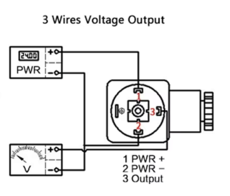
As can be seen on this diagram, Notice the what looks like a Dot, a indicator mark… on the Left, between the Post top and Neg bottom,
as if when you take the top cover off, see mark little mark and then wire according to that, as there is no numbers… well that was exactly wrong way round…
if i take the top plastic off the bottom cylinder… bottom of that plastic was numbers… and this view… so user error, I swopped the cables around… re-installed and it read spot on, like to the cm of water…
Just have to pop to our local Ko-op for some plumbing parts, then have bits to plum in, then wait for package from PiShop so that the white bread board can be build over to port/matrix board.
Whee!
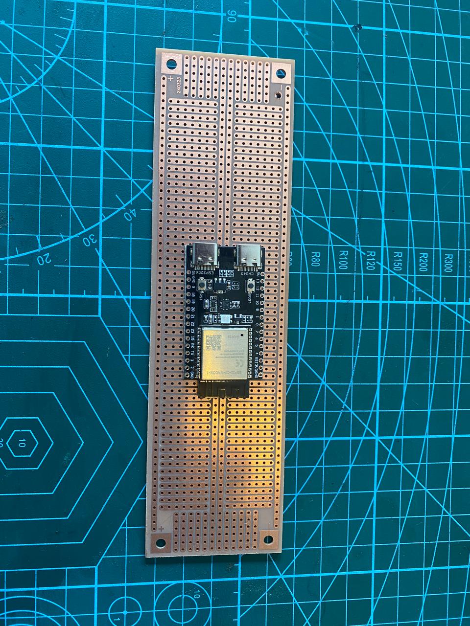
If you are really lazy, these prototype boards are amazing:
https://www.robotics.org.za/PR700
https://www.robotics.org.za/MR777
1 Like
Oh wow… and quite cheap!
In school I always reused Veroboard because it was so darn expensive.
Yup. Locally manufactured. Less than 1/2 the price of Veroboard. And matches the layout of breadboards, so you can prep and debug everything, then just copy/paste onto the protoboard.
1 Like
i like i like,
will get some.
only for this build some proto board i can cut to fit exactly same size/space/holes as a RPi Zero is going to be preferred. also got some plastic spacers that i can put from the top, through spacers through Rpi into screw holes. and designed a little case for the RPi Zero footprint, but with enough space for the wires etc.
Once i have these 3 working my side and the one at a friend then will do another build using a nodemcu as i have a 4th sensor.
G
Much bigger than the idea i got from the picture. Just picked up 4 from Micro robotics in Centurion to play with.
Can easily cut it in halve for two projects.
1 Like
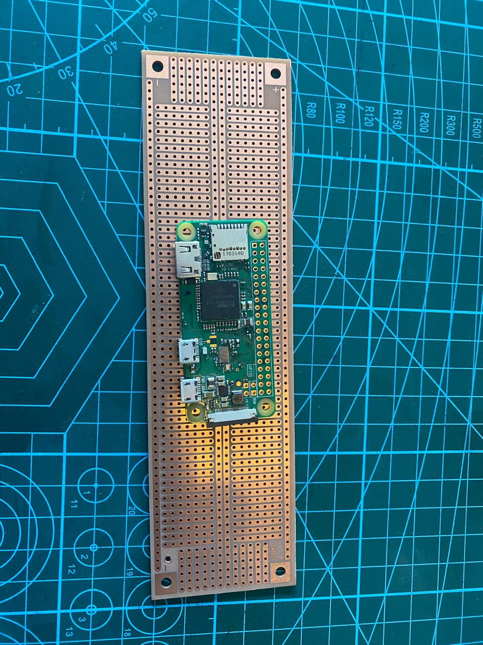
This is what you will have to work with, those two lines down the middle might complicate things if you look at the pin layout of the Zero but THIS might solve the issue.
1 Like
this this board suits the nodemcu platform better than the Rpi…
but still awesome.
G