Letting some smoke out!

The plot thickens.
Techs finally came out today. The box that popped houses the meter. Will obviously need replacing.

2 interesting things:

  1. My meter keypad in my house now shows an error, since the actual meter is bust. Wonder if I’m being charged for the grid usage?
  2. I have 3phase input (only use 1 phase for my house though). When the incoming phases (between the meter and the house) were measured, they are now all “one phase”, suggesting some melting and joining has taken place in the box.

Will have to wait for a new meter to arrive for them to go up the pole and see what’s happened up there…

Do you pay extra for the 3 phase supply?

No, I just have a 50 year old supply (not uncommon in Cape town)

Ask them when they plan to bury the supply cables… (maybe now is a good time??)

Hi Plonkster .

I have the same coffee maker and the same problem . I was also thinking about bridging it

Would it be possible to get the link for the part you ordered , I would like to purchase a few of them .

Many Thanks
Mark

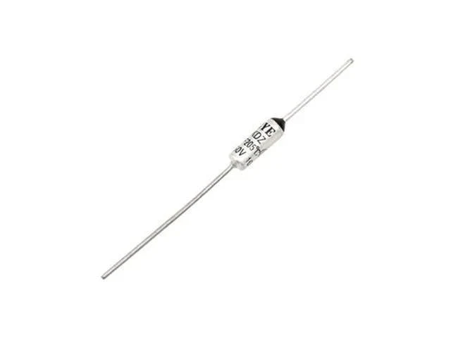
The part you need is this one. At the time, the only place I could get that specific one, was from conrad.de and it would cost about 12 Euro, but it seems Conrad no longer stocks it.

I ordered some cheap thermal fuses from Communica, and discovered shortly afterwards that the issue with those is that the body is not isolated. They look like this, and the metal body is connected to the electrical supply (order them wherever you find a good price, you usually have to order a whole bag anyway):

image

I then made all sorts of plans to try and isolate it, including kapton tape, but I was worried that in a fault condition, the roughly 250°C most commercially available tape can handle, may not be enough.

In the end, I mounted my cheap thermal fuse (I used a 229°C unit, same as the original) so that it sat flush against the ceramic without touching the metal. I’m sure that the thermal transfer capacity is probably less than ideal, and that it would need quite a bit more “soaking” to blow the fuse, but it is probably better than nothing.

Another option is the thermal fuses used for hair straighteners. GHD hair straighteners have a 227°C thermal fuse that appears to have a ceramic body. You can sometimes get them in bags of a few units, but you’re looking at at least R60 per fuse, and as much as R600 (which is about on par with just buying a new Durchlauferhitzer for the machine).

I thought it prudent to post here before I let smoke escape.

All you clever auto electrician sparkies, I need some help please.

I got gifted a set of spotlights for my vehicle, and it has been ages since I’ve last done in install like that. The quote I received for this to happen is just shy of R4k so I said urhmm, let me get back to you.

The issue I’m sitting with is as follows.

Yonks ago I wired up 4 spots on the roof rack with a 4 pin relay for each set. They work brilliantly for years now.

Now I want to add the gifted set on the bumper and use the existing hole in the dash (replacing the current rocker switch with 2 individual ones, one being for rooftop spots, and one for the bumper spots (which will have a 5 pin relay)

What makes these new switches nice is that they (when wired correctly) will emit a constant soft glow which will become brighter when switched on.

And there my hamster spun right out of the wheel because these switches has 4 wires each and I don’t know where they should go.

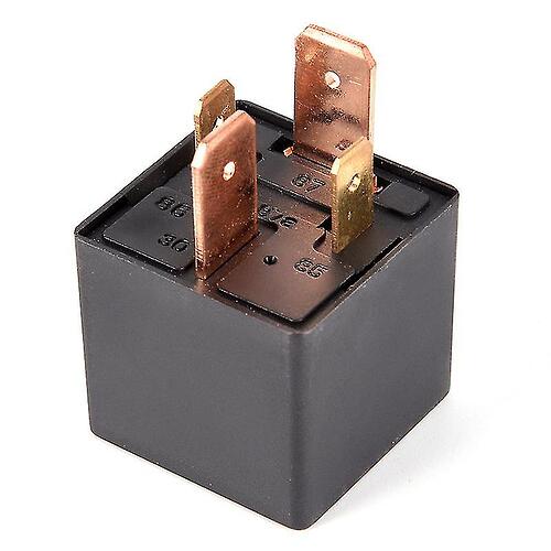
So I understand more or less how to wire up a relay.

Pin 30 will go to the battery + and be fused

Pin 87 will go to the spotlights + wire and the spots negative wire will be grounded

Pin 85 itself needs to be grounded

Pin 86 will have the wire going to the dash mounted switches but needs a return wire to battery +

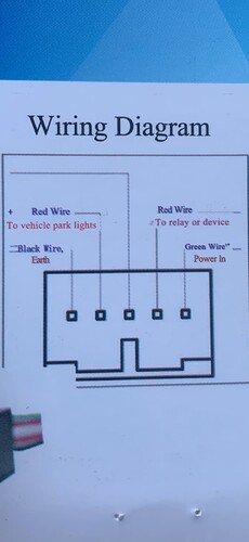
Now these switches… and where do those wires go to. The wire diagram states as follows:

1 x red wire - to relay or device

1 x red wire - to vehicle lights

1 x green wire - power in

1 x black wire - earth

This clashes with how I understand a relay to work. I mean are all 4 these wires necessary? A switch is just there to break a circuit. Surely if I route power through it straight from the battery and to pin 86 everything should work? Or perhaps if doing it this way, the switch won’t be illuminated when off.

How do I do this?

From the diagram, it seems two of those terminals are normal switch terminals that work like every other one, and two terminals are for the backlight, so they need a “constant” 12V supply. For some value of “constant”.

If you get the backlight supply from the circuit that powers the existing dash backlighting, it just works like everything else does.

On the back of aftermarket stereos there is usually an orange wire that is for the backlight of the radio. That is already wired to the same circuit as the dash backlight. That would be the one I would try to use.

I have wired up a test rig this morning with a normal 12V car bulb to start figuring the wires out.

So two of these wires should be from a a positive feed then? I suppose I can join them somewhere on their way to battery +?

One wire (the dim glow one) will always be on, and the other wire will only have power once I press the switch.

And I suppose the red wire that says “to relay or device” and the green one that says “power in” I could join then?

And the black earth wire goes to the battery negative terminal?

Yoh yoh, I think TTT is watching from the shadows to see how I let the smoke out of this R260.00 switch… :laughing: :rofl:

OK, so when I give the switch power from a 12V PSU with the green “positive in” wire and the black negative one, both blue lights on the switch comes on when I press it.

When I release the switch, both are out. So far so good.

And joining the green “power in” and red “to device or relay” wire to + and the black negative wire to negative just results on both blue lights staying on regardless of whether the switch is on or off.

No smoke escaped yet.

Mmmm, what to try next?

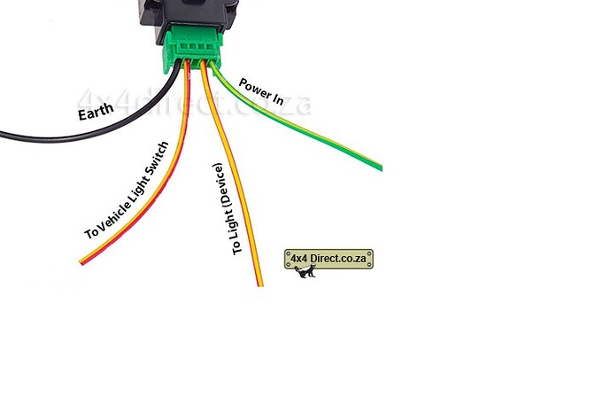
Ok I googled the specific switch’s wiring diagram, and this looks somewhat different.

On the above diagram, it says that the red wire right next to earth goes to vehicle lights. And the red one right next to the green power input goes to relay or device.

Now see this new diagram. I think the terminology confuses me (maybe it says the same thing.

I got this from one of the web sites. Does this make sense?

Red wires should be connected to battery +,

Black wire should be connected to battery -,

Green wire should be connected to load +(load- connected to the battery -),

Blue/Yellow wire can be connected to battery + or not connected(You have the different choice based on yourself).

My understanding of this whole thing, and it may be wrong, is that the two yellow/red wires (or the two that has yellow and red in them) acts like every other switch you’ve used. So the one yellow wire goes to a positive supply, preferably from the existing lights circuit so that it is only powered when the headlights of the vehicle are on, and the other yellow wire goes to a relay that switches the lights themselves. If you only wired these two, like a normal setup, it should work. I am totally guessing but that is what I would expect.

Normally a switch would not require an earth and an extra supply at all. But this switch, again as I understand it, has a backlight, so you can see where it is at night. Therefore you wire the black to ground (no surprises there), and the green/yellow goes to a positive supply that makes the backlight work. Ideally you only want the backlight to work if it is dark, so that one would be wired to whatever turns on the backlight on your dashboard. The park lights is one good source. The other is the circuit that powers the radio backlight (orange wire on most after-market units).

You could take some shortcuts and just wire the green/yellow to the same positive, then the backlight works whenever the vehicle headlights are on. Which is probably close enough.

Ok but I require my spots to work totally independent from the vehicles existing lighting system.

So would these 2 red/yellow wires be the ones to use, one to the battery + and the other one to terminal 87 on the relay then?

What makes this tricky is that the switch has 2 back lights. One should always remain on and when I press the switch the other one also illuminates.

So if I connect the green wire to battery +, then I suspect that both back lights will be on when I press the switch (as it should), but when switching off, both lights will also go off (whereas one should remain on)

Ok here is what I figured out now.

I give green + power and black - power. The 2 red/yellow wires I connected to the light bulb. which completed the circuit.

But the bulb does not come on when I press the switch. But both illuminating lights comes on. So when I take the globe out of the circuit and touch the 2 red/yellow wires together, one goes off (the wrong one though :rofl:

Eish this is difficult for a mamparra like me. Still have all the smoke though.

Ok I got it!!! Just takes me lots longer than technical minded people :rofl:

Pity I cant upload a short video clip here, seems it may in the wrong format as I cannot find it as an attachment once saved on the pc.

But here is how it works:

  1. The red/yellow wire that says “to vehicle light switch” (next to the black earth), join this one with the green that says power in and take these to battery +

  2. The remaining red/yellow (next to green), take this to pin 86 on the relay

  3. Then terminal 85 on the relay, the switch’s earth and the spots’ earth you can all take to the battery - or just ground them individually at their respective locations.

  4. Then what remains is to give terminal 30 a + supply from the battery, and the spots + wire goes to the battery as well.

Done and dusted with all the smoke in tact.

Sorry for stating (the very obvious to guys here) but I did this for in case I lose my handwritten instructions lol!

Cheers everyone and have a good weekend, whats left of it. :grin:

1 Like

Yeah, I think you got it.

Regarding the “two backlights”, I think that’s fairly easy. From a technical viewpoint, you simply put two LEDs in it, one dim and one bright.

The dim one is permanently powered by the “backlight” circuit or the park lights circuit. So that is always on when it is dark.

The bright one you power from the same pin that goes to the relay, so that one is on when the lights are on.

As you noted, since you require the switch to work independently from the vehicle lights, the “to vehicle light switch” wire simply goes to B+, a permanent battery supply. And fuse if of course, since doing that bypasses the fuse protection you would have gained from using the lights circuit.

Thanks for your help Plonkster, always immensely appreciated.

See if this link perhaps works for the videoclip?

https://attachment.outlook.live.net/owa/MSA%3A722e21b6ab406fa9ffb79c885b49c8019accf869c142b45c457ff08239330ae8%40shadow.outlook.com/service.svc/s/GetFileAttachment?id=AQMkAGM4YzkwMAItODkyNy0wODgAOS0wMAItMDAKAEYAAAP6mgJrzzlYQ5bxEevngP50BwDXjFlnj7xLSb9XhkhkCqU4AAACAQwAAADXjFlnj7xLSb9XhkhkCqU4AAAAki6oEQAAAAESABAAOW5pYPG2wUW4IZ1NOXZE3g%3D%3D&isc=1&token=eyJhbGciOiJSUzI1NiIsImtpZCI6IkU1RDJGMEY4REE5M0I2NzA5QzQzQTlFOEE2MTQzQzAzRDYyRjlBODAiLCJ0eXAiOiJKV1QiLCJ4NXQiOiI1ZEx3LU5xVHRuQ2NRNm5vcGhROEE5WXZtb0EifQ.eyJvcmlnaW4iOiJodHRwczovL291dGxvb2sub2ZmaWNlLmNvbSIsInVjIjoiYjdjYjM2OTkwZmVjNGNjOWE0MDBjOTgxMTRkOWViZWYiLCJ2ZXIiOiJFeGNoYW5nZS5DYWxsYmFjay5WMSIsImFwcGN0eHNlbmRlciI6Ik93YURvd25sb2FkQDg0ZGY5ZTdmLWU5ZjYtNDBhZi1iNDM1LWFhYWFhYWFhYWFhYSIsImlzc3JpbmciOiJXVyIsImFwcGN0eCI6IntcIm1zZXhjaHByb3RcIjpcIm93YVwiLFwicHVpZFwiOlwiLTM5Nzg2NDg3OTM1MDQwODU4NzlcIixcInNjb3BlXCI6XCJPd2FEb3dubG9hZFwiLFwib2lkXCI6XCJjOGM5MDAwMC04OTI3LTA4ODktMDAwMC0wMDAwMDAwMDAwMDBcIixcInByaW1hcnlzaWRcIjpcIlMtMS0yODI3LTMzNjg2MTU5MzYtMjMwMTAzNjY4MVwifSIsIm5iZiI6MTcxNTUxMzg4OSwiZXhwIjoxNzE1NTE0MTg5LCJpc3MiOiIwMDAwMDAwMi0wMDAwLTBmZjEtY2UwMC0wMDAwMDAwMDAwMDBAODRkZjllN2YtZTlmNi00MGFmLWI0MzUtYWFhYWFhYWFhYWFhIiwiYXVkIjoiMDAwMDAwMDItMDAwMC0wZmYxLWNlMDAtMDAwMDAwMDAwMDAwL2F0dGFjaG1lbnQub3V0bG9vay5saXZlLm5ldEA4NGRmOWU3Zi1lOWY2LTQwYWYtYjQzNS1hYWFhYWFhYWFhYWEiLCJoYXBwIjoib3dhIn0.uJwnkRoz21tr-Zas-wed2X_le94I3P1cLTQ_fcxxwtsyFMG-DINmzK9Yx-VhuqA5INw1RncyIqH8sosnqOfKtHmBoNd36DDdIvIomEm09S6p0yXjSeXkXOP-QhQaT3Ykfou0CCYzhzMk3fp85ga1r9WwblWOhaWdc4v--ImnBaqdi6YjBCaAIST72X9yckVwo7nIOhgR48kuBvM4HbXTYUC0OpMcCgX6Aa-EhapRmvguNJWw6I0pOeIub5nCsXR4Km6xaSC9yLXO_QAsnRpycAqDuTcJrYy0p5kjj797grfzkeFjOzRxo2Y6-apbnqP3opKskP-190Yu7Olj4JNJ6A&X-OWA-CANARY=X-OWA-CANARY_cookie_is_null_or_empty&owa=outlook.office.com&scriptVer=20240503010.21&clientId=EB1E612E1BDA4700BDA345E9CF428612&isDownload=true&animation=true&persistenceId=2dd871a0-ec4d-4340-9f7f-819a67d72576

Oh my goodness no. Ok I have no clue how to upload. It was taken by an Iphone.

So I will be wiring up my spotlights this weekend and post some pics.

I very seldom drive at night but there is always the odd case where this needs to happen (emergencies etc) and the highway vehicle tyre spiking is getting completely out of hand here in the East of Pta.

We have weekly incidents now and the Triton stood in the back of the line when driving lights were handed out.

So just a little added comfort (rather have it and not need it than vice versa)

1 Like