Option B: But wire them both to the DC disconnect. There should be space?
so you pick Option C haha
Do you mean use one disconnector as in A but have batteries wired as in B
Yes - sorry David.
2 sets of identical cables - 1 set from each battery to the DC Disconnect.
DC Fuses just must be spec’d for total amps of 2 batteries… I don’t think the NH00 has big enough fuses (160a) so will need the bigger disconnect…? Stand to be corrected 
Breakers on the batteries are 125A and I also have a 125A fuse on the cable to the inverter. I Got 160A fuses for the disconnectors as I would rather have the breakers trip first or the main 125A fuse blow first. The 160A amp fuses will protect the cables sufficiently if the pawpaw hits the fan.
Assume 2 disconnectors then - will work fine!
2nd thoughts… If you have a fuse plus battery breaker then do you need a disconnector …
Regards
Mark
I also thought of that but decided it would be best to physically disconnect, maybe its my paranoia. when everything is bolted together its nice to know that you can isolate everything even if the breaker fails.
1 Like
Just checked and you right would need the bigger body size if i wanted to up size the fuse so will have to be one disconnector per battery.
Methinks it is easy to over-complicate things with really cool ideas.
Maybe I’m wrong …
If you have 2 sets of batts on two separate connections it is nice if you want to switch off one.
But, switching off one batt bank does leave the overall charge setting at the amps for two banks, which could be a challenge if the one bank cannot absorb all the amps and BMS disconnects.
Just spitballing - as I had 2 banks on a changeover switch to do exactly that.
What about just putting the two positives through one disconnector that will solve that problem and leave the negative connected straight to bus bar? Still have option to switch off individually with the breaker or disconnect both in emergency. Lets call it OPTION D ![]()

actually one thing i noticed on a lot of victron diagrams is that they don’t really like breaking the negative, possibly because of their boat and vehicle market, so maybe option d is the way to go. Guess there is a lot of ways to skin a cat
Go with that … I break Pos and Neg when I pull that fuse.
As mmaritz pointed out then the fuse might not be enough for both batteries and i would actually need a bigger fuse but that uses a bigger body fuse holder.
Imagine batteries have run flat and inverter and possibly two mppts at mid day decide to charge full steam it could possibly pop fuse. I Need to check what the battery BMS has the charge set at so might be wrong.
I use a fuse holder for + and one for - in multi inverter installs. Size 0 with 160A fuse link per 5kva inverter.
That way I can connect 3 inverters with 2 ketos
1 Like
The fuse, in your case, is now speced to protect the BMS’s, as I got from Revov ASSUMING your cables are sized correctly i.e. 70mm2, which is.
I recall you got 125amp fuses? If so, it should be fine for I don’t think you will run the inverter at max power for extended periods with a low voltage battery. Who does that!? 
yes I put on inverter cable. i understand for inverter load I wont go above the 125A but what about charging as inverter might be charging batteries same time as mppt or does the settings limit that?
is there a reason for this except to completely isolate the equipment, is not isolating the positive enough?
This reference to thick cables are imo creating a lot of confusion. From the Victron documentation…
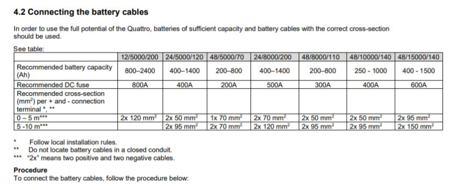
Please look at the first point under the Table, it clearly says, follow Local installation rules. If i look at the SANS regulation, I could safely use a single 35mm cable for a 5kva 48 volt inverter and i do just that, the table recommends a 70mm.
Sans require us to stay below a certain percentage volt drop, and as long as you do, its acceptable and 1000000% legal. I would only consider a 50 or 70 mm cable if my batteries are further than 2m from my inverter.
1 Like
Then you are sorted, one bank or 2, 4, makes no difference, the amps shall not exceed 125amps, as the inverter cannot, so all more banks mean is the inverter can power the loads for longer.
You need one on the positive and negative. We do that on all the DC circuits, battery an pv. It’s the industry standard and taught on most training coarse I know of.
2 Likes
Ignore inverter for now, what if you connect two 250/100 mppt’s to bus bar and they charge full tilt, then fuse to inverter doesn’t matter now the 160A in the disconnector is the weakest point. Just thinking out loud. Please correct me