I use a double pole… One for both. I Don’t do separate breakers. One for input, one for output.
1 Like
That is a teeny titbit worth a ton of gold.
No we are not! ![]()
If I can add do this, unlike what you would usually do, in this case you DON’T want to go as short and thick as possible on the AC side (on the DC side you still do). You want the wiring to have a little bit of resistance, so that you get a bit of natural balancing happening, and so that any minute differences in resistance inside the inverter (eg inside the transfer switch) is completely dwarfed by what is going on outside.
I also learned recently that the DC cabling needs some attention too. If one inverter has a higher impedance in the battery cabling, it runs at a lower voltage, and because the inverters split the power between them on the AC side, the inverter running at the lower voltage has to compensate by running higher amps, which can (at the top end) cause overload if the balance is really off. In my experience, however, the bulk of reported issues is because of an imbalance on the AC side.
Correct. If you do separate breakers, you have to remember that most C-curve breakers use a thermal element to do their work, and those things have resistance, and no two of them is going to be exactly the same… so if you put a breaker in both lines, you are introducing more unknown little bits of impedance.
Correct me if I’m wrong but my thought was to use 4mm cable to my DB for each inverter so two sets of 4mm and because I’m going off grid I will now have my ACin 50A 2pole breaker available.
The 4mm can handle 32A± and the rating for each unit is 27A and with the 50A breaker I cover all nicely.
Is that as clear as mud.
So same length for each AC cable run from inverter to breaker (shared breaker - double pole)?
1 Like
What I’m talking about is people who have two 3kVA inverters, and they they decide to go one wire size up to 6mm^2, to be good and proper, and then they make the cabling as short as possible too, with the same goal in mind, and that ends up being their downfall.
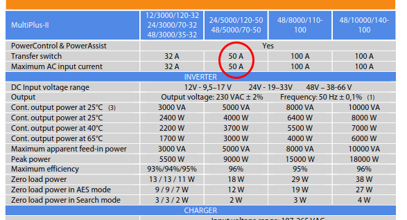
I’m not an electrician. My gut feeling here is that 6mm^2 is better, since the transfer switches in the inverter are technically capable of 50A, and the breaker itself is 50A. Imagine a situation where one inverter is off and the other is in bypass (so only one of the parallel paths are active), then you still want the breaker to protect the cable. For a 3kVA (with the 32A transfer switch) I’d go with 4mm^2.
@JacoDeJongh , what say you?
but if one inverter conks out and everything is supplied through the other it still wont be able to supply more than 27A, it will trip if it goes over.
6mm still is only rated 45A±
so then you size up but now you doing exactly what victron says you shouldnt be doing which is lowering resistance
Yeah, if it is wired purely off-grid, then 4mm^2 will do. If you are going to keep the grid connection (as a kind of backup), and you will occasionally use the grid connection, then I am not sure if that is sufficient. Well, it may be, but then you need to go down with the breaker size on the input side. I do not know, which is why I’d like a sparky to weigh in on that.
Edit: If it is purely off-grid… you don’t even have to wire up the inputs…
yes for the ACin you will need 50A breaker and 10mm wire but that has no effect on the ACout which is where it is sensitive to the cable resistance
As I said i will be removing my ACin breaker as i wont have eskom supply unless i connect generator directly
When running grid-tied with the ESS assistant, the input side cabling also makes a difference. If you have a lower impedance on the one side, you may find that one inverter finds it easier to push the energy into the grid than into the loads…
Or in short… if you are going to run ESS, the input wire size/lengths/balance is also important…
ok i understand what you getting at, you right in a grid connected system. The input wont matter in off-grid
You could make the input cabling 6mm^2 or even 10mm^2, with a suitable breaker. And then you can make the output wiring 4mm^2, again with a suitable breaker (32A). That should be fine. As long as each cable is protected with a correctly sized breaker. I assume this is the setup where 1) there is no ESS, 2) the grid is a backup for when the batteries are really low, 3) or maybe you use a generator as that backup.
that is exactly what i was getting at asking about using separate breakers or one double pole…
separate breakers can protect the cable from each inverter separately, unless you use a 25A2p for example and put the two lives in seperate poles and not break the neutral, but dont think this is safe as you could end up with a hot connection at a off inverter.
Or put a 50A2p and combine the two lives in one pole and the two neutrals in the other pole. Technically if one inverter is off you dont have the correct size breaker then but you also will never be able to generate more power than what the unit can provide so there is very little chance of burning the cable.
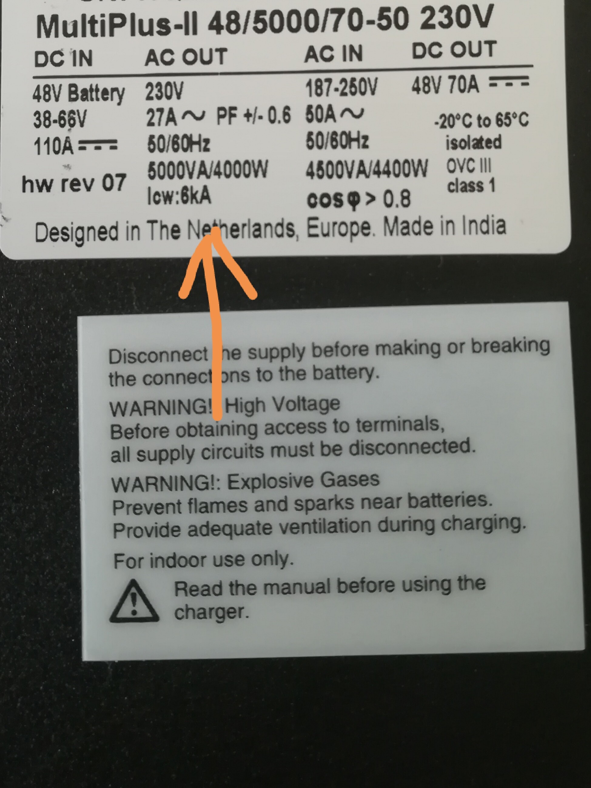
Isn’t it technically 70A? Another 20A can be taken from the DC side and added to AC Out?
70A is the DC charge
Oh wait, you guys are just talking about the AC in cable and not the AC out cable’s thickness?
Both really. The maximum current that could potentially go through there is 50A, but you are right, technically it could be up to 70A if the Multi is also running ESS and is feeding its maximum power into it. But it doesn’t really matter. Just make sure the cable is suitably protected with a breaker.
The trouble is I am not quite sure what is allowed, whether the parallel paths allows you to use a larger breaker (with the potential overheating of the conductor if one of the paths goes open circuit), or if you are supposed to use a breaker sized for one of the cables. That’s the part I’d like a sparky to answer.
And in this case, it is intended to be completely off-grid, so the max current for each side is 22A anyway.
Ah interesting. I guess the first question would be “what is safe”, and not “what is legal”?
Isn’t it possible to put the AC input from Eskom onto a busbar and then run cables able to handle 50A to each inverter separately? Then the cable from Eskom to the busbar have a breaker for its size and from the busbar to the inverters each a breaker for that size cable. The maximum draw that could then be on each of the smaller cables would be 50A and the maximum draw on the larger cable would be 100A but you shouldn’t be able to draw 100A on either of the smaller cables.
I’m not sure how it would be possible to short out one of the cables to then force 100A through the remaining one - I might be missing something quite fundamental here. ![]()
Sorry if what I’m saying doesn’t make any sense, I’m more trying to test my understanding than anything else.
If I put din rail mounted 30A fuses on all the inverter cables and then put into 50A 2pole then it will be safe and those fuses will probably never blow if one inverter goes off but should trip first if not fuses will stop the house burning down and you can still isolate with the 2 pole breaker.
But would like to hear other ideas. Im trying to find SANS code for breaking neutral, because if its not necessary than a 25A 2pole for the two lives will be enough.