Earth leakage sometimes trip during switchover to inverter during load shedding

There’s another nuisance tripping scenario too, where it’s not caused by one circuit exceeding 30mA, but by a small leak through multiple circuits on a common/shared RCD, which accumulate to the 30mA needed to trip the RCD. For example, if 5 circuits were each leaking 5mA then the accumulated total may not reach the 30mA threshhold to trip the RCD, but just one more… bang. And as Jaco says, it’s unlikely to be exactly 30mA, but thereabouts.

If a sensitive clamp meter is placed around each circuit’s wire and the leak(s) differential measured, and multiple sub-30mA leaks are found, then start by tracing where the fault is on the circuit with the largest leak. This will make the biggest difference to the accumulated leaks and is least likely to be one of the electronic leaks that Plonkster mentions (they’re normally tiny).

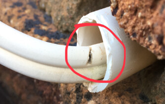
For a laugh at my expense, it took weeks to find an intermittent earth leakage trip that only happened randomly after/during wet weather. Turned out to be caused by the wire for an outside light (earthed) where the insulating plastic was nicked (25 years earlier I guess) and water slowly ran down the wire until it “joined” the wire core with the wall through the nick. It only started when the very old, huge 80A EL was replaced with an RCDO when an inverter was installed.

Something like the photo.
image

1 Like

I’ve seen some pretty huge ones. My Siemens EQ6 coffee machine leaks a whole 4mA.

Also, they leak small amounts at 50Hz. They leak more at higher frequencies, of which there are many sources in a modern home.

Nevertheless, one way I’ve found problematic appliances, is by measuring the leakage, while unplugging/replugging them one by one. In my house, we literally had the “one more leak” situation. Everything was fine, until we bought a new laser printer. Suddenly we were over, but not all the time, just every second load-shedding or so.

I did a mental “what’s the last thing we bought?” thing, unplugged the printer, and it was fine again. Measured the standing leakage, which was 12mA.

How does this work in practice?
I am trying to follow the design. The mains switch feeds the Sub-DB, Ok fair enough.
But to what on the Sub-DB?
Does it feed to the common on the chopover or to the top of the chopover?
Or is there a dedicated Grid supply to the chopover.
How does the inverter feedback to the main DB during load-shedding?

Main Switch, Geyser, Stove, Sub-DB (inverter) on the left of the earth leakage, lights and plugs on the right of the earth leakage.

@Phil.g00 - I’m also curious, but I think the wires don’t necessarily follow the sequence/layout of the switches shown from left to right, which would be the logical way to arrange the switches in a DB.

@rentius2407 - Is there only one earth leakage switch in the whole setup, or do the photos not show the entire DB and a second RCD? Surely the stove and geyser are not without earth leakage, right?

There should be a separate RCD for the non-essential and essentials DBs/rails/circuits.

At the bottom of the photo is a label that says “Alternative…”. Are there more switches below the bottom of the photo?

This SANS 10142-1:2020 (Ed 3) diagram shows the sub-DB and alternative supply (generator or inverter).

This may have been updated in the current/latest SANS 10142-1:2021 (Ed 3.01) to show both a generator and inverter connected.

Hello FlashG.

Here are the photos of the complete Main DB, Sub-DB and then what looks like breaks?
From my understanding is that the power flows Main-DB → Sub-DB → Inverter → Sub-DB → Main DB.
You’ll see the labeling on the Main-DB: Alternative power supply to inverter, and on the right, it says alternative power supply from inverter.

Main DB

Sub-DB

Breakers

Usually as part of the EMI filter on the input. First image I found on google:


Cy being the culprit here. A surge arrestor plug/multiplug usually looks exactly the same (as the 3 caps on the right), with the capacitors replaced with MOVs. (although MOVs and capacitors are the same thing in most incarnations - two plates separated with a metal oxide…) Sometimes they have gas arrestors in series with the MOV which mitigates the tripping issue.

The EMI filter problem is IMO the reason why some countries are moving to RCBOs. The easiest/cheapest solution is splitting up your circuits into sections, each having their own RCD.

(I have not read the rest of the thread, as I think this topic has been discussed to conclusion in a previous thread)

1 Like

I recommend that your installer provides you with a wiring diagram, at least an SLD (single line diagram). Without it, below is my best guess how this is wired…

This looks like a tidy inverter and battery backup setup without solar panels, presuming that the six ports under the inverter are unused PV connection ports.

The thing above the battery is a DC fusebox for the battery - one for positive, one for negative and it looks like there’s a spare fuse in there.

The main DB appears to have non-essential and essential circuits (MCBs) on the same rail, but no SPDs (surge protection devices) and only one earth leakage switch feeding the plugs and lights. If the stove and geyser do not run off the inverter during load shedding (i.e. turn off), then it looks like they are not protected by an earth leakage switch.

The sub-DB is the feed to and from the inverter/battery and the main DB:

  • two lamps (to show power from Eskom or inverter/battery)
  • one SPD (strange location as it should be wired before any circuits (non-essential or essential), so it would offer better surge/lightning protection if inserted in the main DB rail just after the main isolator switch, but before the stove and geyser, as the main DB has four vacant slots)
  • a circuit breaker for current to the inverter from the main DB (it looks like it’s in series with another MCB in the main DB)
  • a changeover/bypass switch
  • another circuit breaker for current from the inverter to the essential circuits in the main DB (lights and plugs to the right of the earth leakage)

Sometimes, the essential circuits are placed in a separate DB, and this is also called a sub-DB, so some installations have three or even four DBs:

  • a main-DB with main isolator, SPDs, earth leakage (RCD), feed to changeover sub-DB, non-essential circuits,
  • a sub-DB with the changeover switch and in/out MCBs,
  • a sub-DB with essential circuits (if the main DB has no space after things added like SPDs, energy meters, extra MCBs). In a large DB these could be located on a separate rail.
  • and if there’s PV then a DC sub-DB with DC fuses, DC MCBs (not the same as AC MCBs)

The only part of this that I question is that there’s only one earth leakage and the location of the SPD (and perhaps that there should be two as per a meeting I had with DEHN recently), but @JacoDeJongh would be a better judge of that.

1 Like

The SPD is not one of my favourites, but at least it has the 275volt Rating and that unit is a double pole, so I guess it should do the job. I would prefer the SPD in the Main DB. You are correct about the EL for the Geyser, It is required by Sans. Its an easy mistake to make, that regulation changed a few times over the last 2 decades, but not so long ago it was implemented again. The geyser should be protected by an Earth Leakage unit.

I see a lot of installers connecting the Geyser without an EL when they split the circuits.

I think that the design is like this:
Eskom is fed to the Sub DB as described.
Then via the Changeover switch common, either ESKOM or the inverter can be selected to directly feed onto the main DB E/L.

Yup. My theory is that a small amount leaks through there, not enough to be a problem, but it gets worse during switchover.

It seems that manufacturers are taking liberties too, slapping a cheap cap in there that may pass as much as a few milliamps at 50Hz, because they are shunting a 35khz (or thereabouts) noise. Add a few appliances like this, and your standing leakage gets close to the nuisance tripping point.

Normally your earth and neutral is bonded, which means there is little voltage across the bottom cap marked Cy, and a larger voltage across the top one.

Then you have a grid outage, and the inverter disconnects the neutral incomer (leaving both floating), and then a split second later it re-bonds T and N. This operation changes the two Cy caps into a voltage divider, only to restore the status quo a second later. Some amount of charge must then bypass the RCD and bugger off over the earth (Edit: but it is a one time thing, a transient, not a real fault).

This sort of filtering is fine in a grid connected house where nothing messes with the TN bonding. The moment you put an inverter in there, they start tripping RCDs.

In severe cases, that’s where you end up with expensive nuisance resistant RCDs. Although Jaco is correct, those CBI breakers do tend to have some nuisance resistance (as does the Hager units), at what is not an exorbitant price.

1 Like

I know Deye and Victron are two different brands, and this may have NOTHING to do with anything, but I have a very strong suspicion that the error I got back then, which made no sense at all to anyone, was linked to the panels and their earthing.

See, when my system was moved subsequently, the earthing of the panels where momentarily not connected (wires from the roof were moved) … and the inverter had the same error when LS took place. Near instant as a matter of fact.

The moment the sparky connected the panels earthing again … ok, truth be told, they missed it. I connected the damn earth wire to the main DB. Yeah, I was that desperate, I worked on the main DB myself.

The problem was solved instantly.

For the record.
Before the re-connecting of the panel earth, after having re-done the main and critical loads DB’s, at moerse cost, I also had the very old CBI Earth Leakage replaced with a brand new CBI Earth Leagake unit.

Eliminating ALL potential causes, “they” said.

So in any and all cases, to eliminate the extreme case of panel frames as a potential cause, even if it sounds silly and even if no relation to anything at all, switch off the panels. Easy enough test.

Maybe my extreme case holds an answer for someone one day when all was tried and nothing worked.

Earthing and tripping issues are not always that simple.
Other times it is extremely simple.
Sometimes it is just weird.

:slight_smile:

Indeed, doubt earthing the panels will do anything here, but yeah. Sometimes it is the things you don’t suspect.

In this case, I don’t think the different brands matter. Both of them bond neutral to earth. With the Victron inverter it is built in, and periodically tested. With the Sunsuck/Dye, it’s an external contactor that isn’t tested. But it functions the same, and the same RCD problems will plague both brands in this regard.

1 Like

Just a question about earth neutral bonding.

I’ve heard earth neutral bonding is a separate component that needs to be installed in the Deye inverter and then the inverter itself needs to be configured by setting SIGNAL island mode.

I’ve looked at the settings on the inverter and the SIGNAL island mode is not ticked. Which makes me think that the earth neutral bond hasn’t been installed as well.

FYI. I don’t have any solar panels, just inverter and batteries.

If there is no earth-neutral bond at the power source then the E/L will be blind and not trip.
Your E/L appears trigger-happy, which is the opposite.

1 Like

They could have made a permanent bond on the output. Not allowed in SA, but a lot of installers do.

Well, they installed it…

Selection_453

You should hear that contactor on the far right click closed, and I believe the indicator top right should show it, when the power is out.

1 Like

He reports that it trips when the power goes OFF. So in that case, it is tripping when the bond is lost (assuming it is not pulling in that contactor).

Thank you plonkster.

Do you maybe know if the inverter should be configured by setting the SIGNAL island mode?

All I know is you should have installed a Victron!

OK, jokes aside. I do not know. But it is easy enough to test. Trip the power, see if that contactor activates. If not, maybe it needs that setting. Sounds like it…

Edit: Remember though, this will in all likelihood not fix the tripping. It may even make it worse… but it is definitely safer that way!