How did you get these two to work?
Have you tasmotised the shelly or running stock firmware?
I’m using stock standard Shelly firmware with the following connections:
Shelly UNI ribbon cable:
- Pin 1+3 – 12V on D5
- Pin 2+6 – common on D5
- Pin 4+5 – not connected
- Pin 7 – status LED on D5
- Pin 8 – beam input on D5
Then the load wires:
- Load 1 outside pin – gate trigger on D5
- Load 1+2 inside pin – common on D5
- Load 2 outside pin – pedestrian trigger on D5
A few setup items:
- Auto off set to 0.2sec, for both channels.
- Input state display enabled, for both channels.
- Button type: detached, for both channels.
- Power on default: off, for both channels.
- ADC range: 30V
Pin 3 (ADC) gives you the voltage of the charger/battery, so if needed you can add an alert if the voltage drops below some user selected value. I opted to use the 30V range since the charger normally gives 13V+ which is slightly above the ADC 12V range.
This is the one I used. You need an FTDI to flash it.
Here’s a single relay that’s USB flashable
ESPHome Firmware
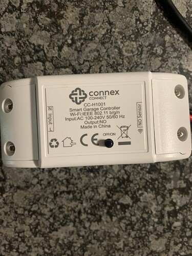
So I got this little unit from Makro. About twice the price of a Sonoff on Takealot. So if it doesn’t work, I’ll get the Sonoff for which there are actually better instructions.
Some help please for someone to whom most of this does not come naturally.
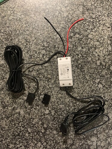
The red and black wires. To which ports on the Centurion D5 do they connect?
And after cutting off the 2 prong plug, can 230V power supply also be obtained from some of these ports?
The last thing that bothers me. The sensing wires with the magnets. Do I really need to mount these also? I was under the impression that motor will provide this information because it has its own magnets. Can I leave these?
The instruction manual is here.
Based on this picture:
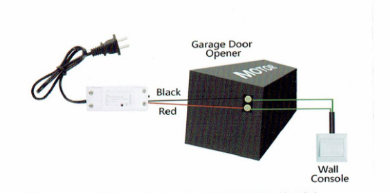
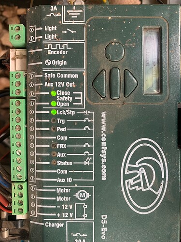
It seems the red and black wires are wired to a relay that simply connects the two wires together when you activate the switch remotely. Therefore, they should be wired to the trigger inputs on the Centurion controller, between “Com” and “Trg”.
For reference, the other pins in the same area, are Lck (if you connect Com and Lck together, the gate is locked and ignores remotes, useful to lock the gate at night), and Ped (pedestrian, if you connect com to Ped, the gate opens only partly to let a pedestrian through). Pretty useful.
You may find that your existing gate opener remote is already wired to Trg.
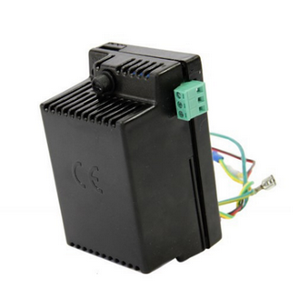
No. There is no 230V on the control board. But to the right of the machine, next to the battery and below the control unit, you will find the charger, and there is a 230V connection on that. It looks like this:
Further to that, the magnet. I have no idea what that is for at all. Seems to me, it is there so the thing knows when the door is closed, so it can let you know?
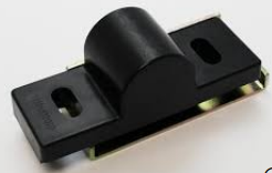
The D5 already has a magnet mounted on the rail, which passes by the “origin sensor”. Looks like this:
and this:
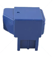
The controller remembers where it expects this signal, and it is usually mounted so it triggers around the 80%-closed point. This helps the controller find the position of the gate without recalibration, if you operated it manually.
I mention this only so you know to mount that magnetic sensor FAR from this magnet, to avoid interference. You want the sensor, and the magnet (which should be mounted to the gate), to be in close proximity when the gate is closed.
Edit: Looking at the board again, I see there is an Aux IO connection, which I suspect (but cannot say for sure) may be programmable to provide a signal when the gate is open vs closed. That would be an easier way to get a signal that the gate is closed, without mounting the magnetic sensor. BUT… I also suspect that magnetic sensor is wired to a GPIO on the board of that little sonoff-knockoff, and if I recall correctly, the GPIOs are not isolated from the mains. Soooo… I would probably not take a chance with this. But if you used a Sonoff SV with Tasmota, I’d absolutely use that instead.
Plonkster, your assistance is always most welcome and even more appreciated!
Trigger - red wire
Com - back wire?
Or does it not really matter which goes where, just a switch?
I am assuming/hoping that this can be overridden by the WeLink app’s functionality, because it is pretty handy indeed! I’ll first try just the plain old default (for me) mode and once I muster up more courage, I’ll try these modes.
I suppose also I’ll mount that sensor magnets, just to make sure everything is done by the book. It is kinda crucial for me to know whether the gate is open or not.
Probably doesn’t matter, but my OCD will require that black goes on Com.
Just like a multimeter yes. Thank you!
You can get the Open/Closed state from the Status LED and terminal. Might be able to hook the reed switch onto that.
Off is closed. On is open (partial and fully).
Opening and closing are indicated with various flashes. The ESP Home firmware that I posted earlier interperates the flashes and show the state in Home Assistant, including No Mains when there’s load shedding.
That Connix controller doesn’t look like it runs off the gate motor battery, so if you don’t already have an inverter it’s something to keep in mind.
I’ve attached the manual for your reference.
0_07_A_0059 D5-Evo Installation Manual-18092013-BMCT-web.pdf (3.2 MB)
Thanks for all the replies. I tackled this Friday afternoon as it was a quiet day at work and without too much trouble, I managed to do this by connecting exactly as Plonkster said.
This is definitely something I will look into, as the app is a little lost without the sensors which I secured with only the double sided tape they came with and will not stay there for ever.
I have to say though, that the alert from the app notifying you of the gate opening or closing, is less than 2 seconds. Love that!!!
The tricky part came when I wanted to go one step further by ordering Siri to open and close the gate for me seeing as I don’t have Alexa or Google Assistant or whatever. This took a while and some Youtube’ing but I did it, a mamparra like me lol and it is an amazing feeling voice commanding my gate open. ![]()
I couldn’t get it right with the CBI Astute controller unit which controls my geyser though. There is a step missing to add the commands/scenes to Siri although the software appears the same.
Next up is a Connex wifi camera and spotlight combination for my gate area, seeing as I have now “mastered” its app/software.
I would only do that if I am sure the GPIOs on that unit is isolated from mains. That is not always the case. If the device uses a non-isolated power supply, it is not isolated from the mains. That is okay, as long as you use the reed switch that came with the thing, but the moment you wire those wires to something that is also connected to other things (the battery negative of the motor, in this case, as everything is common-ed to battery negative in these units), you’re looking for trouble.
If you want to do this, consider using another 12V relay in the middle: So the Centurion controller closes the relay when the gate is open, and these contacts then replace the reed switch in the Connex.
What is the reed switch that you guys are referring to? Pardon my ignorance.
Reed switch
(they have pictures, so my explanation cannot compete ![]() )
)
This thing:
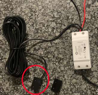
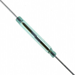
It is a magnet switch, it has two small “reed” contacts inside, and bringing a magnet close to it causes them to latch together.
Inside it has a little glass tube like this:
And other common places you will see this is on the door sensors for your alarm system.
Since it is only a switch… you can chop it off and replace it with any other switch that does the same thing: connect the two wires together when the gate is closed.
Aaaaah much obliged thank you!
Your thoughts please guys.
So the past weekend I assisted a friend to also install one of these Connex wiifi controllers on his gate motor.
Worked flawlessly for a week and then he had a battery issue and lifted the motor housing of a little too aggressively resulting in the wire of the reed switch fixed to the housing breaking of out of the plastic covering the switch. So no chances of joining it.
Can these OEM reed switches be replaced with say alarm door contact reed switches?
Yes.
Well, just to cover myself, I’ve never seen one of these things myself, but looking at the pictures… almost certainly yes.
I will provide feedback here. Think we’re going to try it.
