Your relay idea might work, the Lock unlock can be wired through the Normally Close of the relay. When the relay is de-energised, the gate it unlocked, when the relay is energised the gate is “Locked”
For the pedestrian opening a normal trigger through the second relays “Normally open” should be all you need. Remember that the pedestrian opining has his own auto-close timer and it can be programmed for a shorter period than the normal auto-close timer.
Been thinking, when I thought about the relay’s I was thinking about connecting them like on a RPi… where I have many 5V and Gnd and signal pin’s.
Thinking these GPIO pins just read data on the signal line, not sure I can send a instruction out via it… some research time. … or get another SV and a relay and just prototype it.
G
Something to think about, instead of relays, are opto-couplers. Extremely cheap, and if you know the polarity (ie whether the input on the control board of the gate motor is pulled up to 3.3V/5V/12V, or pulled down to ground, which is the more common thing to do), you simply wire the opto appropriately to do the same thing.
In my experience, also with D5 Evos, the control connections (eg for the beam, or for the trigger) are pulled down to ground (aka battery negative, 0V) to do the work. So connecting an Opto coupler across it with the arrow of the NPN transistor towards ground will do the trick.
On the lock, I assume the point on the D5 Evo board is normally open, and it locks when closed ?
and the Pedestrian is purely a momentary close point, which engages the pedestrian open (limited distance with a auto close again)?
Do you have a specs for the board?
Looking like the sonoff SV won’t work, so thinking D1 Mini, but might have to add a Back converter to handle the voltage, the D1 mini is 3V, the output from the D5 board is 12V.
Want to place a “little” order with Communica,
G
Nope, it needs a bridge between Negative and the pin. Once the bridge is removed the gate locks. I use the normally close contact of a relay to keep it unlocked, once i energise the relay, the bridge is opened and the gate locks…
… playing with idea to pull the sonoff SV out, replace with a raspberry pi zero + buck converter (to manage the voltage drop required). and then 3 relays… or if i can get my head around octo couplers as per Plonkster. by using the Pi i can also potentially input the gate position etc, got all those open pins.
They both use the same ESP8266 chip. Well, a very similar one at least. The SV has 3 easily accessible GPIOs in addition to the one that presently drives the relay, and the SV has a voltage regulator on board so you can power it directly from the 12V battery (the D1 mini needs a separate power supply to make the 3.3V).
I’d think that you simply need to configure the GPIOs as relays (using tasmota terminology) and that will cause them to go high (3.3V) when turned on and low (0V) when off. If you’re going to use opto isolators, then you simply drive the opto with the 3.3V (you probably need to throw a 220Ω resistor in series with the opto I’d guess, to limit current to around 5mA).
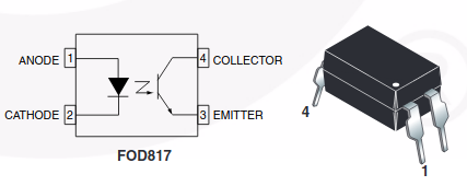
Screenshot from a data sheet. The GPIO drives the “LED” on the left, through a resistor. That switches the transistor on the right (think of it as a small solar panel attached to the base terminal of the transistor which forward-biases it). That transistor then conducts in the normal manner. The one in the picture is NPN, the arrow on the emiter (bottom pin) points outwards, which means you connect the negative side to this. The other side (collector) would go to the more possitive side, which in this case would be the connection on the D5 control board.
Result, when you turn on the “LED”, the transistor pulls the terminal on the D5 to ground via that NPN transistor. And there is no physical connection between the two, so it does not matter that one runs at 3.3V and the other at 12V (or whatever).
Could I ask if you would mind looking on Communica for the correct Opto isolator and required resisters. I checked the sonoff SV outputs 3.3V on the V pin of those GPIO pins, implying it’s to low for the Relay’s.
this will be the one option, 2nd is still a buck converter, nodemcu or api zero and 2channel relay, one with esphome, other with arabian and a simple put-on application. and lots of open gpis pins and possibilities.
Oh, and not to add too much detail and potentially confuse the issue… but you get opto-triacs as well. Instead of a transistor, it has a TRIAC on the other end, which you can use to switch AC. But the current capabilities are low so you usually use a small opto-triac to switch a larger triac… and once you get to this point you’re probably better off going with an SSR (solid state relay), which is basically the exact same thing
@plonkster your opto idea is very plausible. I used it the e other way around. The LED output from my D5 dr8ves the opto and that pulls pins on my Sonoff SV high. So i have the LED output from my gate motor available in HA. You can determine open and closed positions from the flashing patterns. I coupled this with a mag switch on my alarm and use a D1 mini as a virtual keypad to my DSC alarm. So i have physical open and closed data from that in HA.
Yup, I got the opto idea precisely to tie the LED output of my alarm system into a Sonoff-SV. In the end I figured out I can get away with just a voltage divider to get the signal down to 3.3V, so I went “the cheap” way. But it is technically much better to use an opto.
Your name almost gave me a heart attack. My parents lost over a million N$ last year due to the shenanigans of a name sake… I suppose it is a very common name
… all configured on nodemcu board, buck converter to drop the volt from 24->5v for the 3 relays, all poc’d on bench… and shown to work inside HA… get to the gate, and nodemcu does not seem to be able to reach wifi in house, although the sonoff sv does… will go back and check/confirm this again tomorrow, if confirmed will just use the 2 open gpis pins on the sonoff sv to do what i wanted. can still all work,
G
I have the same problem. When I power up the D1 Mini, all the relays fire at the same time. Photos & Video
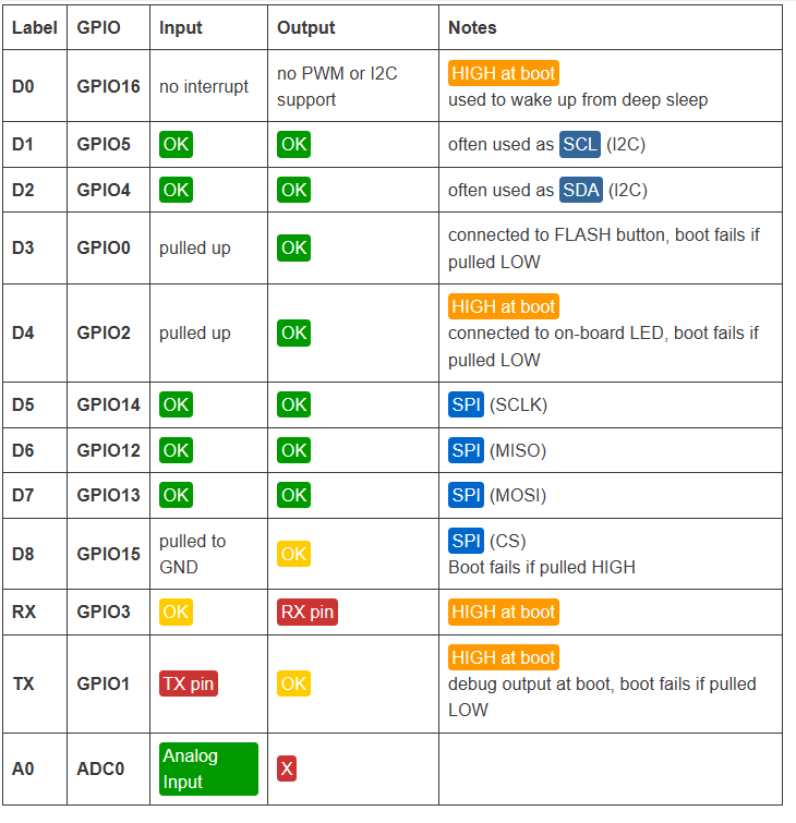
On the D1 Mini the D0 pin can’t do mode: INPUT_PULLUP. With that commented out it just always says On. Any advice?
What pins do you use for the relays and to read the status.
Looking at the pictures , I suspect that you might have a floating input and will need a pulldown resistor.
This pin guide is quite useful when working with ESP boards