Pylontech - template sensors for HA

Hi all,
I may sound silly, but I wanted to share template sensors I created for my Pylontech battery bank consisting out of 4 x US3000B batteries.

Currently, there is no time remaining or time till full calculations coming from Batteries (BMS) or Venus and since I don’t have BMV. Because of that I created template sensors for HA.

Please comment, rip it apart, give suggestions, laugh at me, share if you have anything that is better, etc :slight_smile:

  1. Battery - Current Remaining Capacity (Ah)
- platform: template
  sensors:
    battery_remaining_capacity:
       friendly_name: "Battery Remaining Capacity"
       unit_of_measurement: "Ah"
       value_template: >-
         {% set t = states('sensor.battery_soc_victron') | float %}
         {% set u = states('sensor.battery_current') | float %}
         {{(296*(t/100)) | round(0, default=0 )}}
  1. Battery time remaining under current load
- platform: template
  sensors:
    battery_time_remaining:
       friendly_name: "Battery Time Remaining"
       unit_of_measurement: "Hr"
       value_template: >-
        {% set c = states('sensor.home_ac_consumption') | float %}
        {{(236*48/c) | round(0, default=0 )}}

I have taken 20% of the total capacity, as I have the 3000B version…the figure for 4 x US3000C would be 280 (capacity - 5%)

  1. Battery Recharge Time
- platform: template
  sensors:
    battery_recharge_time:
       friendly_name: "Battery Recharge Time"
       unit_of_measurement: "Hr"
       value_template: >-
         {% set x = states('sensor.battery_remaining_capacity') | float %}
         {% set y = states('sensor.battery_current') | float %}
         {{(2*(x/y)) | round(0, default=0 )}}

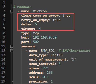
The above assumes that you have following Victron modbus sensors created:

  • sensor.battery_soc_victron
      - name: "Battery SOC Victron"
        data_type: uint16
        unit_of_measurement: "%"
        slave: 225
        address: 266
        scale: 0.1
  • sensor.battery_current
      - name: "Battery Current"
        data_type: int16
        unit_of_measurement: "A"
        slave: 100
        address: 841
        scale: 0.1
  • sensor.home_ac_consumption
      - name: "Home AC Consumption"
        data_type: uint16
        unit_of_measurement: "W"
        scan_interval: 5
        slave: 100
        address: 817
        scale: 1

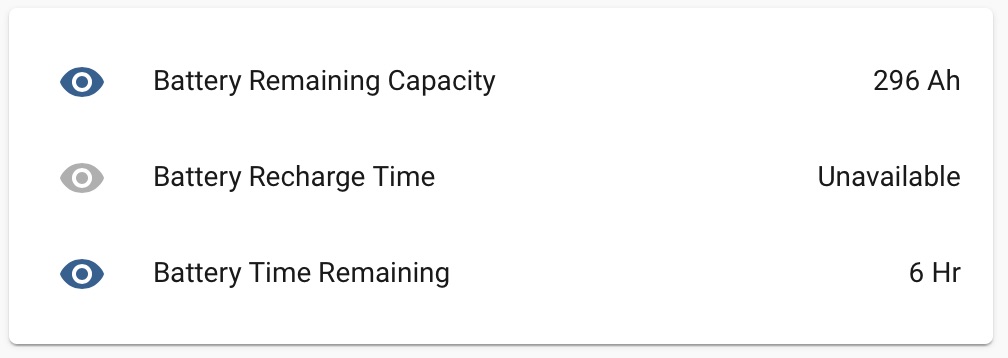
This is the results:

Current “problem” is the update interval. Modbus sensors update every 30 or so seconds and make the template sensors to update as well which can seem erratic at times.
Possible solutions is to create sensors specifically for the calculation and make them update every 15min or 30min…
Maybe creating moving average sensor from the results? Opened to suggestions and new ideas :slight_smile:

One other problem that I need to see how to resolve is - if the value from the calculation is negative (recharge time is negative value when not charging hence the time comes up as -36 Hr for example) - I would like it to change to “Not charging” or something like that…
work in progress…will update

And here is almost final version

- platform: template
  sensors:
    battery_recharge_time:
       friendly_name: "Battery Recharge Time"
       value_template: >-
         {% set x = states('sensor.battery_remaining_capacity') | float %}
         {% set y = states('sensor.battery_current') | float %}
         {% set z = (2*(x/y)) | round(0, default=0) %}
         {% if z == 100 %}
           Battery Full
         {% elif z > 95 %}
           Battery almost full (>95%)
         {% elif z >= 0 %}
           {{ z }} Hr
         {% else %}
           Battery Discharging
         {% endif %}

I’ll test and see what is the Amperage battery will accept at around 90% SoC and see if it needs to be adjusted

Hope it helps someone :slight_smile:


and this is when its 0

You can change a sensor’s update interval. Will it help if I give you the code?

Yep, I can definitely see to use it in some way or form, thank you :slight_smile:

So in your sensor (or for modbus as a whole I think), you can add this line: scan_interval: x (where x is number of seconds).

I’ve added scan_interval: 5 for the sensors I specifically need to update quickly (for PV management).

… not having unpacked it, but only noticing high level, you connecting directly to the bus, pulling information from VenusOS…

any chance you willing to show how/where you do that connection, would like to copy/past and see this on a sandbag page on my HA.

G

Here is my modbus.yaml that is just stored and referenced in configuration.yaml :slight_smile:
Change the IP address to your Venus IP and enable modbus in services on Venus

  - type: tcp
    host: xxx.xxx.xxx.xxx
    port: 502
    name: "victron"

    sensors:
      # System
      - name: "Home Power Consumption"
        data_type: uint16
        unit_of_measurement: "W"
        scan_interval: 5
        slave: 100
        address: 817
        scale: 1
      - name: "Grid Power"
        data_type: int16
        unit_of_measurement: "W"
        scan_interval: 5
        slave: 100
        address: 820
        scale: 1
      - name: "Inverter Temperature"
        data_type: int16
        unit_of_measurement: "C"
        scan_interval: 60
        slave: 23
        address: 3304
        scale: 0.01


      # Battery
      - name: "Battery voltage"
        data_type: uint16
        unit_of_measurement: "V"
        slave: 100
        address: 840
        scale: 0.1
      - name: "Battery Current Victron"
        data_type: int16
        unit_of_measurement: "A"
        slave: 100
        address: 841
        scale: 0.1
      - name: "Battery Power Victron"
        data_type: int16
        unit_of_measurement: "W"
        slave: 100
        address: 842
        scale: 1
      - name: "Battery SOC Victron"
        data_type: uint16
        unit_of_measurement: "%"
        slave: 225
        address: 266
        scale: 0.1
      - name: "Victron ESS Minimum SOC"
        data_type: uint16
        slave: 100
        address: 2901
        scale: 0.1
        unit_of_measurement: "%"

      # MPPT Array
      - name: "PV Voltage"
        data_type: int16
        unit_of_measurement: "V"
        slave: 245
        address: 776
        scale: 0.01
      - name: "PV Current"
        data_type: int16
        unit_of_measurement: "A"
        slave: 245
        address: 777
        scale: 0.1
      - name: "PV Power Victron"
        data_type: uint16
        unit_of_measurement: "W"
        scan_interval: 5
        slave: 100
        address: 850
        scale: 1
      - name: "PV Yield today"
        data_type: int16
        unit_of_measurement: "kWh"
        slave: 245
        address: 784
        scale: 0.1
        precision: 1
      - name: "PV Max power today"
        data_type: int16
        unit_of_measurement: "W"
        slave: 245
        address: 785
        scale: 1
      - name: "PV Yield yesterday"
        data_type: int16
        unit_of_measurement: "kWh"
        slave: 245
        address: 786
        scale: 0.1
        precision: 1
      - name: "PV Max power yesterday"
        data_type: int16
        unit_of_measurement: "W"
        slave: 245
        address: 787
        scale: 1
        
      # Pull power from Grid
    switches:
      - name: "Charge / Supply from Grid"
        slave: 100
        address: 2700
        command_on: 6000
        command_off: 30

No with regards to update interval, I can always create “another” sensor here referencing the same reading and giving it a different name with the scan_interval of e.g. 600 and use that for the calculation so that I’m ok with.
Next problem that I am facing is - once battery is charged 100% it doesn’t work because charging current drops to 0 and one can’t divide by 0…
So this is still work in progress :slight_smile: and I am opened to ideas

some questions…

I have the 2 x Pylontech US2000 2.4kWh Li-Ion Batteries

I also have 2 x MPPT’s (Victron BlueSolar MPPT 150/35 ), one with 6 solar panels (East Facing) and one with 3 panels (atm, want to upgrade this one to 9, it’s North facing)

What screen layout do you currently have for the above, any chance you can share… actually never shared a HA screen layout/definition, could be interesting to do.

G

This is my current HA screen, pulling info via mqtt…

I am monkey see, monkey do, but I added this after the last HA update failure, to try and fix things back then.

Thought I share it here:
image

with my two MPPT’s ?

They have addresses on VenusGX : 258 and 260 - how where in the below do I insert this, I’m guessing I have to duplicate the below to two copies and update the names to say “PB Voltage” → “PV Voltage (258)” as a example, “PV Current” → "PV Current (258)

      - name: "PV Voltage"
        data_type: int16
        unit_of_measurement: "V"
        slave: 245
        address: 776
        scale: 0.01
      - name: "PV Current"
        data_type: int16
        unit_of_measurement: "A"
        slave: 245
        address: 777
        scale: 0.1
      - name: "PV Power Victron"
        data_type: uint16
        unit_of_measurement: "W"
        scan_interval: 5
        slave: 100
        address: 850
        scale: 1
      - name: "PV Yield today"
        data_type: int16
        unit_of_measurement: "kWh"
        slave: 245
        address: 784
        scale: 0.1
        precision: 1
      - name: "PV Max power today"
        data_type: int16
        unit_of_measurement: "W"
        slave: 245
        address: 785
        scale: 1
      - name: "PV Yield yesterday"
        data_type: int16
        unit_of_measurement: "kWh"
        slave: 245
        address: 786
        scale: 0.1
        precision: 1
      - name: "PV Max power yesterday"
        data_type: int16
        unit_of_measurement: "W"
        slave: 245
        address: 787
        scale: 1

G

In some cases, you can use the values from com.victronenergy.system instead (see the spreadsheet).

spreatsheet

what spreadsheet, damm did I miss a share again, hehehe

G

CCGX-Modbus-TCP-register-list (2).xlsx (44.8 KB)

1 Like

Look on the Victron Energy website, I think it is under Downloads, White papers. That one is always up to date with the latest released version of Venus.

The unreleased one, roughly corresponding with the beta version of Venus, is in github, in the dbus_modbustcp project… should you want to go looking for that one instead.

After testing all and observing, I came to a conclusion that the below code is the most optimal for the need I initially had.
Hope someone finds it useful :slight_smile:

- platform: template
  sensors:
    battery_recharge_time:
      friendly_name: "Battery Recharge Time"
      device_class: 'battery'
      value_template: >-
        {% set x = states('sensor.battery_remaining_capacity') | float(0) %}
        {% set y = states('sensor.battery_current') | float(0) %}
        {% if y < 0 %}
          Battery Discharging
        {% else %}
          {% set y = ([0.1, y, 200]|sort)[1] %}
          {% set z = (2*(x/y)) | round(0, default=0) %}
          {% if z > 591 %}
            Battery Full/Not Charging
          {% elif 591 > z > 550 %}
            Battery almost full
          {% else %}
            {{ z }} Hr
          {% endif %}
        {% endif %}

P.S. “Battery Full/Not Charging” message caters for the ‘sensor.battery_current’ being a value of 0…so battery is either not charging due to the low “sun” conditions or its full.

I’m pulling values via mqtt atm,

just wanting to play around and see the similar values via the dbus.

I see in spread sheet the address column, and then to the right the dbms-obj-path… now to map this to my mqtt topic of (N//solarcharger/258/Pv/V)

G

Values should be exactly the same regardless of the mechanism used to obtain them (MQTT vs modbus).