The one with the lowest value will “trip” first and the other will not. So in this case your 30A fuse will always blow first before the breaker trips.
That’s true but the inverter is only rated 27 amps so the fuse should never blow but if both inverters exceed 50A the breaker will trip.
This is just an idea.
Fuses introduce a bit of resistance into the path. But they are usually fairly consistent, so that might even help.
We may be overthinking this completely though. I need to figure out the answer to that question I mentioned.
haha yes i think so too. Its like having an extension cord from a generator we not worried about it as its a 3kw generator so the cable is safe i think its the same with the cables from inverter, you never going to get more out of it than its rated.
Sans on neutral disconnection, technically your earth leakage unit does this, but if everything is not on earth leakage will need a main double pole.
6.9.2 Disconnection of neutral conductors
6.9.2.1 A neutral conductor shall not have a single-pole disconnecting
device.
6.9.2.2 In the case of a single-phase circuit, the disconnecting device shall
disconnect live and neutral. In the case of a multiphase circuit, the
disconnecting device shall disconnect all the phase conductors but need not
disconnect the neutral conductor in an installation connected to a supply
system in which the neutral conductor is earthed direct (see the TN system
in annex K).
6.9.2.3 A disconnecting device used in a supply system in which there is no
direct connection between earth and any live conductor shall disconnect all
the live conductors (see the TT and IT systems in annex K).
NOTE In a safety supply, none of the conductors are connected to earth, so any
disconnecting device in such a circuit has to disconnect all the conductors.
found this but not sure if it applies to parallel multi installations
6.9 Disconnecting devices
6.9.1 General
6.9.1.1 Each installation shall have one disconnecting device to disconnect
the entire installation, except in the case of multisupplies or more than one
transformer supplying the installation where each supply shall have its own
disconnecting device. There shall be a notice fixed next to each such
disconnecting device indicating that the installation has more than one main
switch-disconnector.
Even in parallel I will not go under 10mm per unit for the simple reason, I always use breakers equal to the passthrouh rating. In the event that one unit fails and needs to be removed, the cable to the remaining unit should still be able to handle maximum pass through.
And if you installing off grid and there is no pass through and all loads on Critical output?
I also used 10mm on my ACin as manual says it must have 50A breaker. But off grid you don’t have this.
Then I will stick to a 40 Amp breaker with 6mm on both units. Leave some head room for using the 20 plus amps from a 6kva generator and add the 16 amp from the inverters DC side.
Edit: keeping in mind that at some stage one unit might be doing all the work plus passing through some current from a genarator.
It’s way easier to change a breaker (up or downgrade) than to redo wiring so I have 10mm installed for upgrades if needed.
That is a good point and I already have the 50A 2p with 10mm maybe I will just double up the 10mm and make it my output cable instead of inverter input, so if eskom ever begs me to reconnect and feedback solar it will be easier to go back to grid tied. Will do some more research still got lots to install before i tackle that.
2 Likes
Update time.
Managed to install the big 250 mppt. And a new PV DB, went double the size as that mppt can take more than the 4 strings I’m going to add so future proofed it.
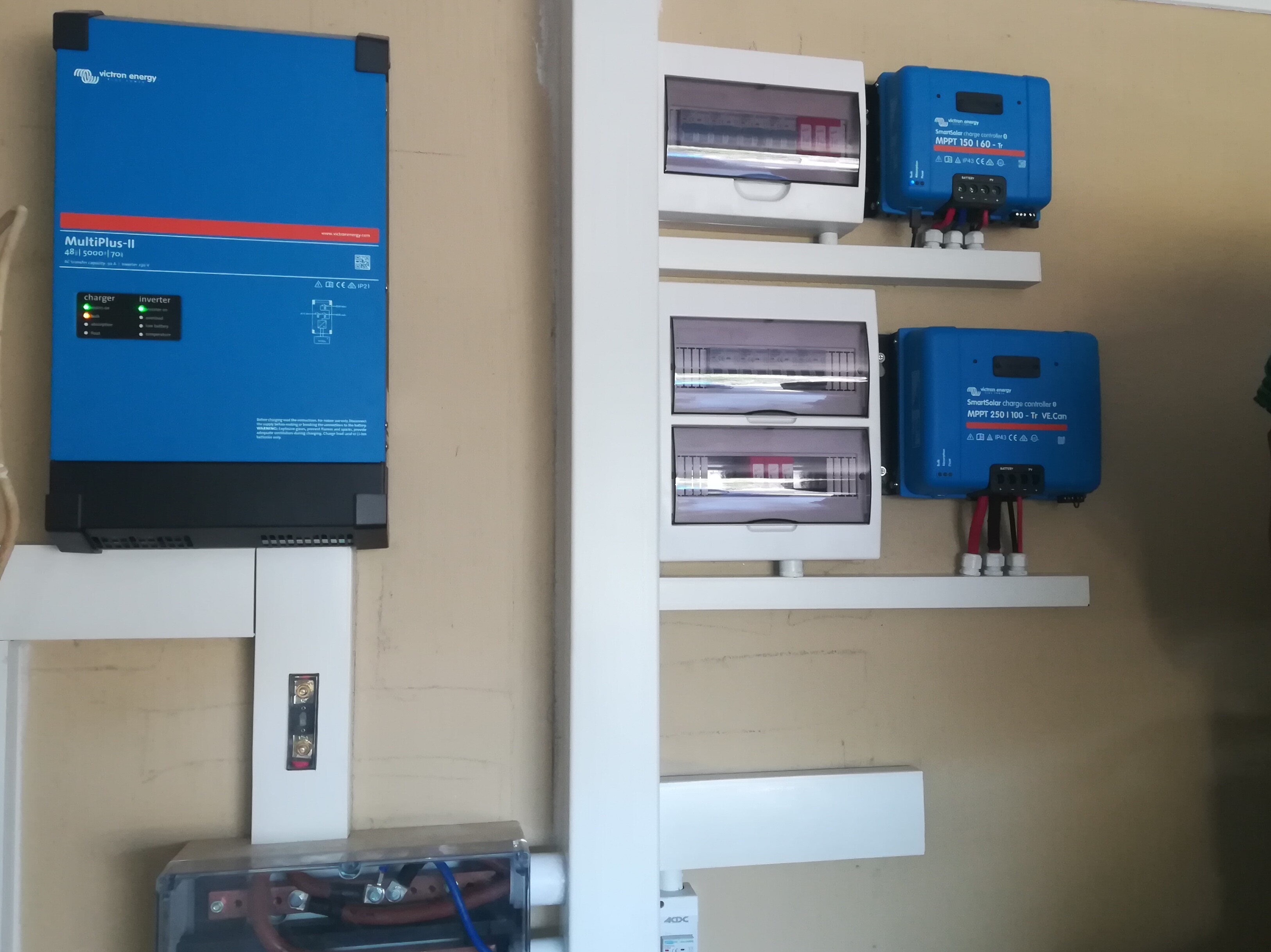
7 Likes
Very neat
@Louisvdw you mentioned before that you had one string east and west on one mppt if thats correct.
How does the opposite string affect the active one, for instance in the morning how badly does the west string affect the output?
I’m thinking of using the extra two string available on my 250mppt to put east and have the 4 strings west. It can handle it as its only about 11amp per string so just under the 70amp max. But if its affects the west output to much would rather put another mppt for east as I originally planned.
There is not much of an affect. A study on on this showed below 5% if I remeber correct. See the thread Solar panel direction East/West vs North for the link to that study as well as data from my own.
MPPT or Maximum Power Point Tracking is just that. Your MPPT will track the max producing string and optimise for it. Any other string migh not be that optimised, but it still produce power. In the morning your East string will be tracked and in the afternoon the West string will be tracked.
1 Like
There was a discussion on this a while back, and definitely, if your MPPT can deliver the amount of amps you want, you just want those amps available for longer (i.e. you don’t want more overall available PV) then doing this is fine. In the mornings the MPPT will probably set the voltage too high for the West panels to produce anything and in the afternoon again for the East panels. During midday it will be a funky mixture of the two.
This I think is a good strategy to follow if your MPPT is the right size, you just want more reliable, or available for longer, PV. I think this is the case for most people. If however, you need more power in total, and your MPPT is already clipping amps, obviously the only way to solve that problem is by getting another MPPT for the extra panels.
I suspect the efficiency loss you will experience if you combined North and West/East panels might be a little more, because there is more of an overlap in the time when the panels produce. However, you will never generate less if you combined the strings like this (at least, I can’t see how). It is only when you start mixing orientations inside a string where you might actually be better off never having done it I believe.
1 Like
This only works if all the panels in the string face the same direction.
1 Like
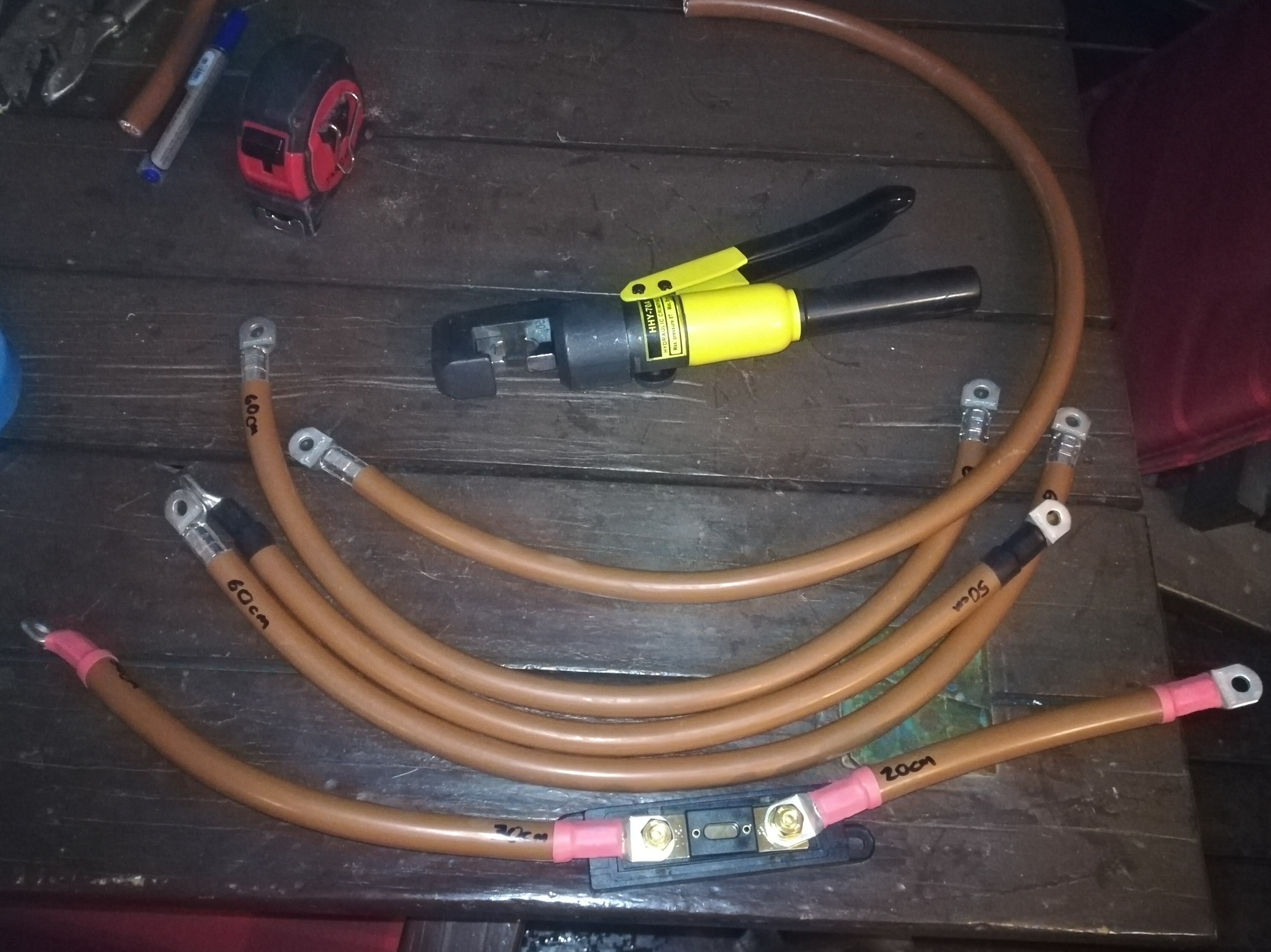
So started duplicating cables for the second inverter and battery and I’m 1 cable and 2 lugs short 
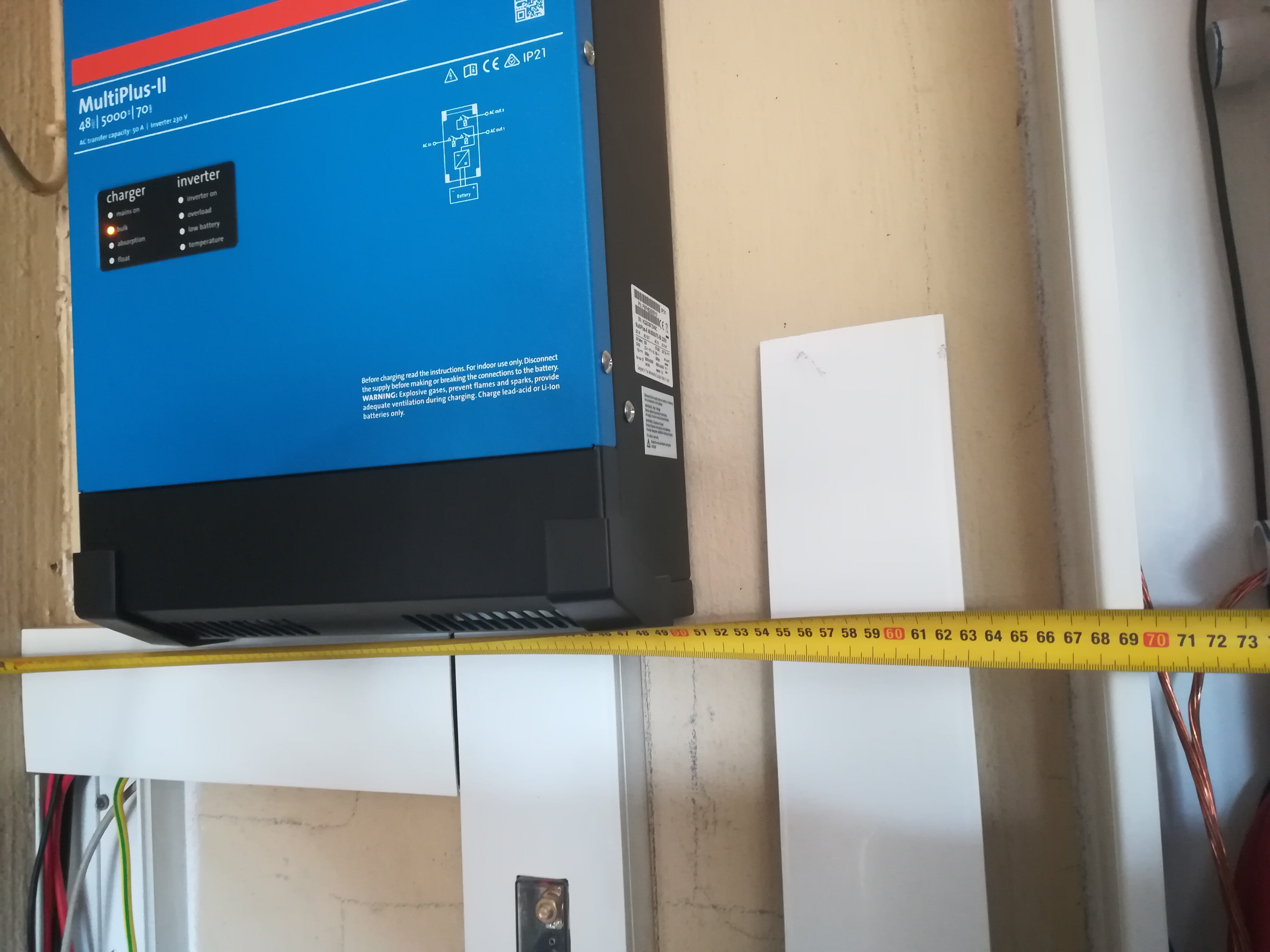
Also have come across a problem which I didn’t exactly foresee. When planning for space for the second inverter I didn’t put the busbar close enough to the second wall so now it’s a bit to far and the second inverter is going to be quite low.
The other option is to move the first inverter over and place the side by side but then I don’t have enough air gap around the inverters. If only I had made the trunking from the roof just a little more to the right.
Last option which might look a bit weird but will be the easiest to cable is to just make up a frame so that the second inverter sits infront of the first and slightly to the right so you can still see all the indication lights.
Let me know what you think.
How much air gap would you have in option 2 ? ![]()