So, after some time, I finally decided that I need to point out a few “points” in SANS10142 that has to do with PV installation compliance.
I have now had a few electricians making a statement that SANS does not cover DC or PV installations… This is becoming a problem for me, as it clearly does and most electricians issuing a CoC does not know what’s going on!
The problem with DIY PV installations is that they are illegal, if you read the Acts and Regulations regarding electrical installation, it clearly states that these installs have to be done by a qualified person.
I am not going to address the DIY solutions here… What I want to point out is a few “problems” that keep jumping out when dealing with compliance, and I am open to discussion to see if the interpretation I have is the correct one…
So let’s jump in:
[Format will be “Statement” and then a separate ("|") and pointing to clauses (if available)
AC and DC conductors shall not be in the same trunking | 6.1.10, 3.85, 6.1.7,6.4.1, good practice
Protection devices shall be DC rates (see other post, very well explained) | 7.5.1.1
Correct protection and cable selection for batteries | 7.15.1.1
All DC cables must be labelled accordingly | Clause 7.12.x somewhere
The neutral shall not be earthed beyond an earth leakage | 7.16.4.5
a TN-S system shall not be converted to a TN-C system | 7.16.4.6
If a system is a hybrid and can operate in island mode, the earth leakage on the plug circuits shall be tested when inverter is islanded. Where applicable a earth-neutral bond (via relay) shall be installed to ensure proper operation of the earth leakage during grid loss events. | Clause 7.12.3
Notice/Labelling to indicate alternate supply, this includes that all “back-up” circuits be specifically and clearly labelled. | Clause 7.12.2.1
Alternate supply short circuit current taken into account with main incoming short circuit currents | Clause 7.12.2.3
Earth Leakage installed after the inverter output | Clause 7.12.2.6
Correct Surge Protection has been installed on all DC and AC components as required by the lightning risk assessment
Neutral bar shall be split between council supply and on-site supply | Clause 7.12.3.1.4
Solar panel frame and structure shall be bonded to the consumer earth | Clause 7.12
Where single core conductors are used, such conductors for each circuit shall be tied together at intervals to ensure identification, unless another suitable arrangement is employed. | Clause 7.12
All DC (string cables) to be in conduits or where applicable affixed to the structure (no matter if they are UV rated)
All DC string cables to be labelled accordingly and voltage levels indicated on both the cable ends and the Distribution board. Note both operating voltage (max) and allowable voltage for the system on the DB board.
In addition it shall be recognised that the supply from each inverter,
battery arrangement and PV panel (or identified clustered group), constitutes
a supply, and requires arrangements similar to point of supply, which shall
include switch-disconnection arrangements and shall comply with 7.12.5.
Does the CoC specifically include mention of the Alternative Supply? Has all the appropriate boxes been ticked and the description made specific to in the PV installation?
This is not an exhaustive list on SANS10142, but a few points that is not covered by most installs. I have one in bold there that might cause a lot of discussions (it was copied verbatim out of the code)…
So, if you are doing installs or getting a sparky to check the installations, please consider the few points above. With the CoCT sign-off by a Pr. Eng requiring the engineer to sign-off on the SANS compliance, it can become a bit sticking point…
I feel that point 1 and point 6/7 will be one of the bigger discussion points, with quite a few opposing views on these ones.
I had a supplier specifically state that you must do a hardwire on the E-N on the Ohm (Sunsynk) inverter output… Well, SANS does have other opinions on that matter…
I don’t think we’ve argued about TN bonding yet on this side of the forum divide
Also, we’re fairly heavy on the blue side of things, and the blue inverters do a relay test and often cause people a lot of heartache as it exposes existing issues, shortcuts and the occasional couldn’t-be-bothered-to-find-that-neutral. Almost ironically, most electrical installs are in far better shape AFTER installing a Victron inverter than it was before… cause it forces you to do it right.
I would say that my installs comply mostly up to nr12. From nr 13,14 and 15 I would love more detailed info as I see no SANS referance.
DC I have noticed is a very neglected topic in general and I for one was guilty of that as well. Since I started with solar I made an effort to look onto DC and I was surpized on what I was missing all the time.
TN = Terra Neutral. It means neutral is tied to an earth spike.
S = Separate. It means the earth arrives from the supplier on a separate conductor. So you have three wires coming from the transformer to your kiosk where it connects to your house (I will assume single phase for simplicity).
C = Combined. It means you get only two wires from the transformer, and the neutral wire also doubles as an earth (it is already earthed at the transformer).
In most installations where earth and neutral is combined, you are expected to install an earth spike on the premises, and earth neutral a second time. From this point on you then run a separate earth conductor. The installation is then known as TN-C-S (combined up to a point, then separate).
When the regulations say you cannot convert TN-S to TN-C, what they really mean is thou shalt run separate earth conductors always and never combine them with a neutral. The last time earth and neutral is allowed to meet is either at the transformer (if it is a TN-S setup), or at the kiosk (if it is a TN-C-S setup).
So, after some quiet time, I decided to do a bit of a “visual” follow-up on the original post.
Note that I have been using the list as part of the compliance checks that I have been doing.
I hope this can start a good discussion with installers, trainers and with other engineers doing compliance checks.
Please have a nighttime read and let me know what should perhaps be added or clarified.
I did NOT touch lightning compliance (as this is a design thing!).
Very nice document. I do like all the warning labels you have in there as that is not always so clear from the regulations what should be on labels. (e.g. example labels)
The only minor nitpick would be that you don’t need to fuse the negative DC side (of the battery), positive is sufficient. But you must have an isolator for both poles. Most people simply use one of these NH1 fuse holders and fuse both sides, but technically you could put a simple link in the negative side and it would be legal.
This is 100% correct, but I have opted to not include that option in the document as I was tired of adding ALL the different design options here. I believe that stating the standard would be good enough for a competent person to interpret and comply.
(And yes, this is the type of discussion that I want and then one can jump into best practice).
The “problem” the Pr. Eng actually have is that the CoCT sign-off only looks at NRS compliance, while there is a “does this comply with SANS” block to tick, how far should the Pr. Eng go into this? Note that engineers and technicians aren’t actually trained on SANS10142! So if the engineer looks at the CoC and it states all is in order, you CAN argue they satisfy the CoCT requirement.
I do not subscribe to that view, thus I did study SANS10142-1 (and -2), NRS097-2-1, The PV installation standards in IEC (now also in SANS) etc. So I do frustrate people by failing some installs (or requesting rectification) on the SANS compliance point…
I did note the requirement to label everything with the rated voltage. I’ve never seen that done and I didn’t think it was part of the grid code… but you quoted the exact line number for it. I also have a modbus-rtu cable with some AC cabling (but it’s surfix, so technically in it’s “own” raceway), and in the test bench (which was built in a different country) only the positive side of the battery is fused and switched…
Jip, That surfix is an interesting one when it comes to compliance. The Surfix is a cable and not a conductor as defined by the standards, which means that one needs to relook at the standard wording and requirement.
I would not fail an installation where the cables (not altered) are installed next to conductors of another type. This is especially important where AC, DC and communication cross.
One must assume that when it is finally released that it will still have this requirement.
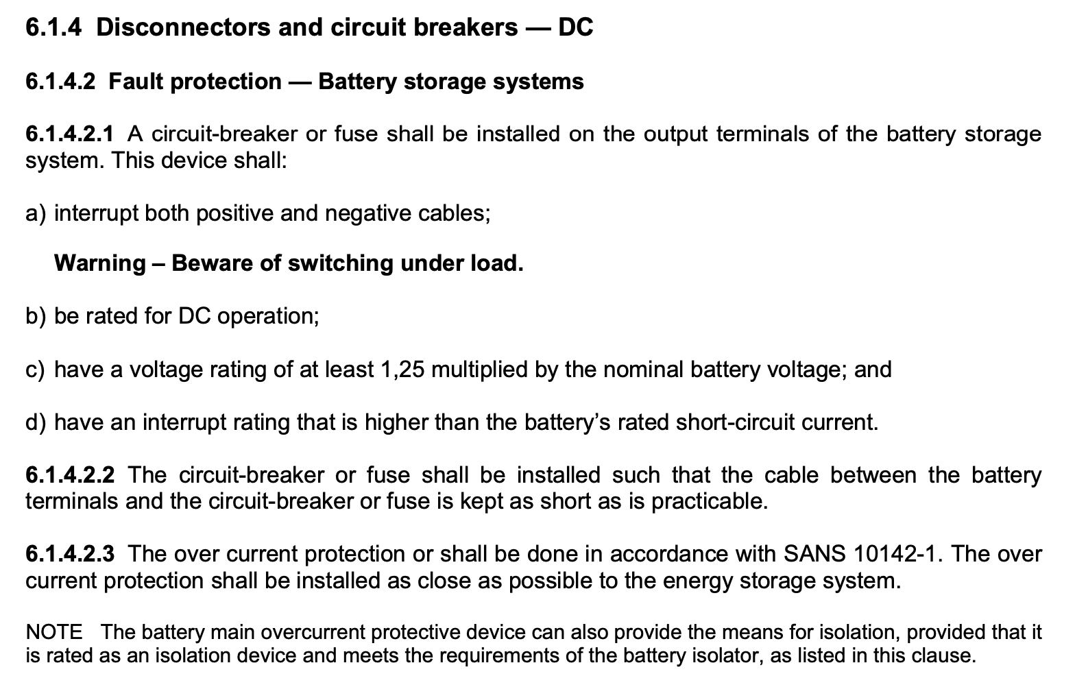
As worded, does this mean if the negative is interrupted by a breaker on the battery (eg. eTower with integrated breaker) that a fuse on the positive would be sufficient to meet the requirement to “interrupt both positive and negative cables”?
And in the case of a BYD or Hubble which have internal circuit breakers, do we assume that they do not count and we instead have to fuse or otherwise add interruption to both the negative and positive in order to comply with this (withdrawn) standard?