The genuine and the clone will likely be nothing alike. With relays/contactors like that the contact material is incredibly important. If you skimp on those, you weld contacts at far lower than rated currents. With a safety critical application like this, I would be very cautious…
1 Like
There is other overload protection in duplicate.
I say they are clones because these relays are priced above 200Euro apiece.
For that price differential, I am prepared to test it out.
Edit: I would also mention that other BMS’s using this sort of relay, won’t be using 200Euro versions of it.
I am getting info overload (Chinglish would help, but the documentation is straight Chinese) and I need to cut through the bumph:
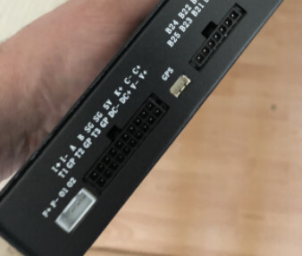
This is the BMS I ordered, with no special extras, supposedly it has RS485 comms as standard:

The supplier has indicated these are the 485 connections:
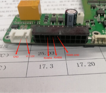
Along with the message:
![]()
This is my photo that would seem to correspond:
My question is: Do I need a 485 to USB converter or a TTL to USB converter? Or what do I need and how do I find out? Baud rate?
@Louisvdw, any suggestions?
I know the question was directed to Louis, but yes you would need a USB to Rs485 converter to communicate to for example a Gx device…
If the device that you want to use for communication/control/monitoring has its own Rs485 port, you dont need any converter
1 Like
The JKBMS is a funny one in that. It needs a RS485 thingmagic that is plugged into the RS485 socket. But it is actually just a TTL->RS485 converter which you then need to use a RS485 → USB converter to plug into your GX device.
You can do that route (that is how I have it at the moment), but for all information I have found and test from some users you can just use a TTL->USB directly which I think is better and cheaper (KISS)
![]()
Edit: There are newer models so it might have changed.
1 Like
I asked the supplier if it was RS485 to USB or TTL to USB.
The answer I got was: “Yes”.
Edit: I have ordered both now, is there an argument to try a particular one first because it’s less likely to damage something if it’s wrong?
This is not battery-specific, but usually when you see A & B labelled, that’s the differential lines of RS485 (typically at 5V) which need a real RS485 to USB converter, with RX & TX being TTL (5V or lower logic) and finally RXD & TXD being a real COM port at + & - 13V, but these are rarer and rarer now.
But YMMV, especially with Chinese-labelled products. ![]()
Can you find another seller with the same device? They sometimes have better docs.
1 Like
RS485 and TTL are both 5V based system, so it should be fine to try either.
RS232 is a 12V system, so the best to always try very last.
@mariusm is correct in that in that A/B labels indicate differential lines.
But his statement on Chinese labels is even more correct. It is never as you think. ![]()
1 Like
Ship’s computer: Captain, the enemy is attacking!
Captain: What!? From the Starboard or Port side!?
Computer: Yes!
1 Like
Thinking aloud for my own education, so mods please delete if derailing or unhelpful
I think technically RS-485 can be between -7V to + 12V according to the standard?
If not wanting to destroy any adapters and/or attached devices, safest might be to check voltage levels between gnd and A/B on the BMS? Changing designs, bad documentation, and the 12V pin in the photo would make me nervous. Scanning through some of the pdf’s I also saw “TTL/RS-232” indicated somewhere and RS232 I understand to actually have -12V to +12V standard while TTL should be 0V to +3V/5V so it should not really be synonymous?
With that said, various sources (1, 2, 3, 4) suggest that the RS-485 port on the JK BMS is actually at TTL levels (0-3V) and that the JK RS-485/CAN adapters available will be used to convert to the voltage levels and invert logic where required for RS-485 or CAN.
So, unless connecting from the JK BMS to a confirmed RS-485 port, a TTL-USB will likely be sufficient. (until the next undocumented design change… see the comments on baud rate change from 9600 to 115300 in the “source 3” link).
1 Like
Yes, it is sources like these that led to the confusion.
The supplier now confirming it is a 485 > USB converter and that I don’t need to consider the baud rate.
485 is a 5V system, but the spec allow for a 7V range on top of the 0-5V which give -7V → +12V
So it is a bit confusing in that it allows for up to 12V, but it actually is a 5V system and most controllers will work on that 5V.
See end of the Signals paragraph RS-485 - Wikipedia