3 posts were split to a new topic: Multiple shunts for DC system
We have a new beta build that adds Renogy BMS to the driver.
If you are a Renogy BMS user please give it a test.
1 Like
I have 2 * 16celll LiFEPO4 battery packs with DalySmartBMS, 3 Multiplus 3000/48 and Venus OS 2.81 on a RaspberryPi4.
I can see only one DalyBms, what can i do to see the second BMS?
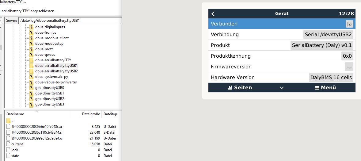
You need to revert back to VenusOS V2.73 and you will see both BMS.
There is an issue with it in the V2.80 and only 1 BMS is displayed. I am working on a fix, but until then stay on 2.73
1 Like
Ok thanks, i have made a update to 2.82, but it also does not show the second one.
So i have to go back to 2.73.
anything above 2.73 will only show 1 BMS for now.
Now with 2.73 both BMS are there, THANKS.
But i still have one probleme.
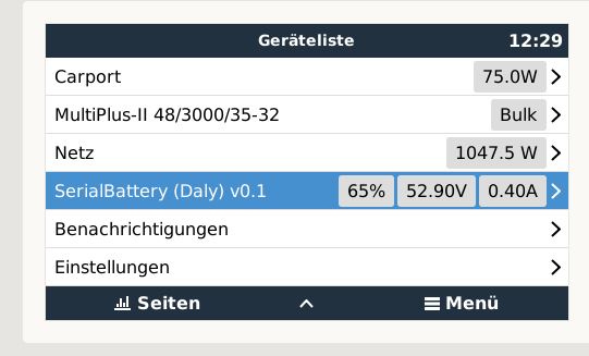
The one DalyBMS returns values with the opposite sign. Therefore, with the one bms charging and discharging is swapped. in the picture the left BMS is in reality discharging, not as shown charging. the problem is in the bms of corse. can I multiply the values by -1 in the configuration?
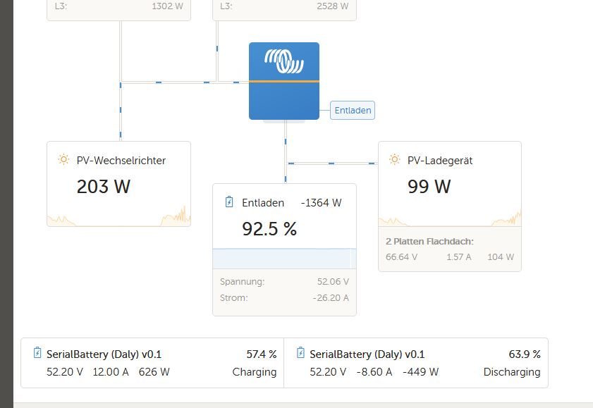
Some of the Daly BMS models have their current flow swopped and the driver have a option in the settings that you can set to invert the current value so that it shows correct.
Your problem is that you have 2 different models used in the same system, and the driver setting is for the system, not per device. So if you swop it for the one, it will also swop for the other.
Hi @Louisvdw,
Thanks for your efforts and excellent work.
Did you have a chance to check/test this one:
Seems promising with all-on-board stuff with a very high power rates.
I have one just arrived, but do not have (yet) batteries to test it.
Sorry if I have missed this, but is there anything one can do in order to provide the needed information for adding support for a new BMS (like this one)? Probably having Venus OS installed on RPi, connect to the BMS with USB to RS485 and run some scripts/commands to dump some data.
You best option will be to get the communications protocol from the seller. If that is not available you will have to use sniffing tools to try and get all the serial commands, but that is not so easy.
Each manufacturer use their own setup. Most do not follow Modbus stricly, so they all do their own thing and if you don’t have the correct command the BMS will ingore all your comms. So there is no dump tool, although I have thought about an idea that can help in that regard in the future.
Hi @Louisvdw you made a very good work, thank you very much!
Now i use the version 2.73 and i want to update to 2.8X but then i can´t see my two DalyBMS.
Is there a chance to update the venus os in the future and get both bms displayed?
Hi @model3rider
Yes I am working on a fix. We need this to work in the 2.80+ firmware to be able to handle the multi banks feature as well
Wow this has been quite some journey Louis, bravo on your work. I am brand new at this and have been trying a few different options to read the BMS from two distinct server rack batteries. One, the Jakiper can be read by solar assistant with its Serial to USB connection option so I expected the serial driver for VenusOS to connect, but it did not. Any suggestions on how to trouble shoot a connection failure, or is the Jakiper’s BMS not supported?
Sorry to the simplistic questions, if you can point me in the right direction to figure it out for myself (short of disassembling the battery at this point) I would love the lesson.
Thanks
Ed
Hi Ed
The thing is with these BMS manufacturers is that everyone use their own communications protocol. They all implement their own version of a MODBUS based protocol but they are all different. If it is not one of the BMS that we have already implemented it most likely will not work without quite a bit of tweaking. Is it using the same bluetooth app as any of the existing working BMS?
If you have the comms protocol for that battery? Is it available to download?
If it is available I suggest you create a ticket (of the github page) for it with the protocol information and then see if there are intrest from other users as well.
While I am getting all of the components for my system, trying to find the most suitable BMS. Reading the thread, JBD seems to be the most tested one.
JBD SP25S003-16S, 100A (seems the same like the Overkill solar 16s version) is the one that I am planning to have on a 16S, 100Ah LiFePo4 battery. It comes with two 10AWG wires (B- and C-), around 15cm.
It is the one from the (they call it) factory store:
I am planning to have this connected to 5000VA Multi.
Have someone tested this BMS? Does it really handle 100A continuously (which will be my target max)? Are the stock jumper wires big enough for 100A or they are short enough to bother?
Saw some members are using the models with the high amp automotive relay (JBD-AP20S003S-200/300A).
I found another JBD model rated at 150A cont. and 400A peak. Seems not so popular: JBD-AP21S001V1:
@Louisvdw, can we expect all three are compatible with the driver?
Good to have some pros and cons and other feedback from users of each of them.
Sorry to rise this old post, just curious what is the cli command to get this.
You can run ‘dbus-spy’
With regards to the BMS options JBD would be the most tested, but also the most flexable. Any JBD model will work (Overkill Solar is just a rebranded JBD).
I would suggest you get a BMS that is rated higher than what you will need. It is never a good idea to push any electronics to it’s limits if you want it to last a long time. I’ve been running a Multiplus II 3kVA of a 100A JBD on the stock cables for a long time. No issues. For a MP II 5kVA I would suggest a 200A BMS. Remember that the MP II can peek much higher than their rating and your BMS should be able to handle that.
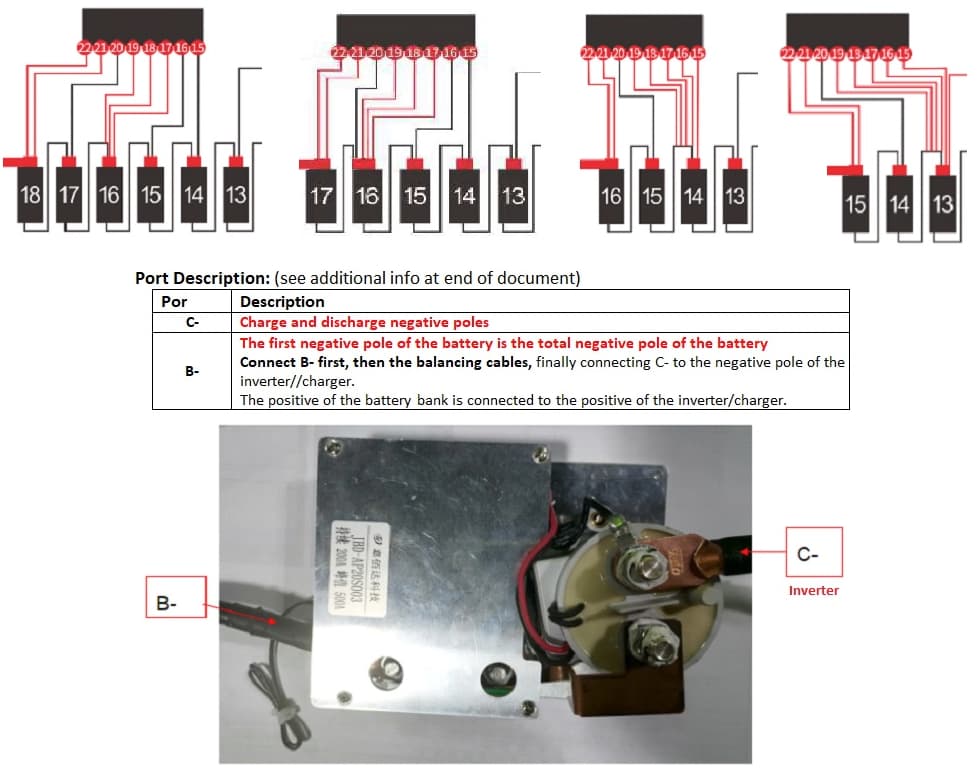
I like these, they can take 24v (8 cells) OR 16 cells (48v) OR one can push the envelope and even go 18 cells (48v). Jip tried it all. ![]()
The secret lies in how one connects the balancing wires.
When you order, ask them to add an RS485 port.
Why?
Then you can use the RS485 port to USB to connect to the Venus, using Louis software to help better manage the battery.
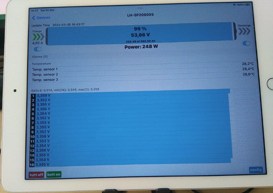
AND you can use the UART/Bluetooth port to connect your phone, Andriod or iPhone, at the same time to program the BMS on the fly, see what is going on per cell.
Here I’m using an iPad to see the data whilst the BMS is connected to the Cerbo/Venus. Apple version has more functionality than the Andriod phone version.